Flip through any ADCP datasheet and you will find the beam angle listed — typically 20° or 30° from vertical — tucked between the frequency and the depth rating. Most buyers glance at it and move on. But the beam angle is not an arbitrary design choice left over from the engineering team’s first prototype. It represents a deliberate trade-off between three things that matter to your data: horizontal velocity resolution, vertical velocity resolution, and how much of the water column you can actually measure before side-lobe interference contaminates the signal.
This article explains exactly what beam angle does to your measurements, why most manufacturers settled on 20°, and the specific scenarios where 30° might actually be the better choice. The goal is not to make you an acoustic engineer — it is to make sure the next time you see “beam angle” on a datasheet, you know what you are trading off.
The Geometry: What Beam Angle Actually Does to Your Measurements
An ADCP measures velocity along each beam axis — the component of water velocity projected onto the line the acoustic pulse travels. But what you want is Earth-coordinate velocity: east, north, and up. To get from beam-axis velocity to Earth-coordinate velocity, the instrument must decompose the measured signal into horizontal and vertical components, and that decomposition depends directly on the beam angle.
The mathematics is straightforward: if a beam is angled at θ from vertical, the along-beam velocity measurement contains roughly cos(θ) of the vertical velocity and sin(θ) of the horizontal velocity. At 20° from vertical, approximately 94% of the along-beam velocity contributes to the horizontal component. At 30°, this drops to approximately 87%. That 7 percentage point difference may not sound dramatic, but it propagates through the coordinate transformation — when the instrument combines four beams to calculate the full velocity vector, the horizontal velocity uncertainty for a 30° system is measurably higher than for a 20° system, all else being equal.
What does this mean in practice? If your research question is about horizontal currents — and most ADCP applications are — a 20° beam angle gives you a better signal-to-noise ratio in the horizontal component. The vertical component, by the same geometry, is slightly better resolved at 30°. Since most oceanographic and hydrological users care far more about horizontal velocity than vertical velocity, the industry has largely standardized on 20°.
But geometry is only half the story. The beam angle also determines something arguably more important: how much of the water column you lose to side-lobe interference.
Side-Lobe Interference: The Hidden Constraint on Usable Profile Length
Acoustic transducers do not produce perfectly collimated beams. A portion of the transmitted energy — typically 5–15% — radiates in directions other than the main beam axis. These side lobes are an unavoidable consequence of transducer physics. They matter because a side lobe angled outward from the main beam can reach the bottom before the main beam does. When it reflects off the seabed, the return signal is much stronger than the scattered return from water particles, and it contaminates the velocity measurement in the affected depth cells.
The vertical extent of the contaminated zone depends on the beam angle. The side-lobe interference boundary — the depth above which your data is unreliable — occurs at a distance from the bottom equal to approximately (1 – cos(θ)) × water depth. For a 20° beam angle, this is roughly 6% of the water depth. For a 30° beam angle, it is roughly 13–15%. In 20 meters of water, a 20° ADCP gives you usable data to within about 1.2 meters of the bed. A 30° ADCP loses the bottom 3 meters. In 10 meters of water — a typical river gauging depth — the difference is 0.6 meters of lost profile versus 1.5 meters.
This is not a small effect. For a shallow-water discharge measurement, losing 15% of the water column near the bed — where the velocity gradient is steepest and the contribution to total discharge is substantial — introduces a significant extrapolation uncertainty. The 6% loss with a 20° beam is more manageable, requiring a smaller extrapolation from the last good cell to the bed. This, more than the horizontal velocity resolution argument, is why most general-purpose ADCPs use a 20° beam angle.
Beam Angle and Array Configuration: Four Beams, Five Beams, and the Janus Geometry
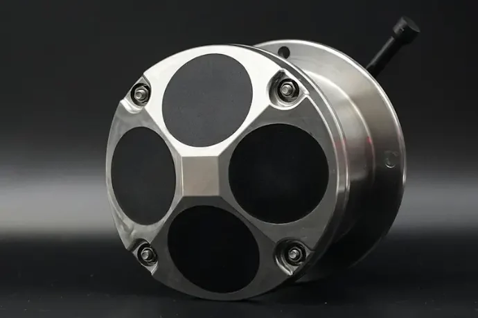
Nearly all modern ADCPs use the Janus configuration: beams arranged in symmetric pairs on opposite sides of the instrument axis. A standard 4-beam Janus ADCP has two pairs of beams, each pair measuring opposite horizontal directions. This symmetry cancels certain error sources — notably, if the instrument is tilted or if there is a uniform vertical velocity component, the paired beams see opposite projections of the error, and it cancels out when the beams are combined.
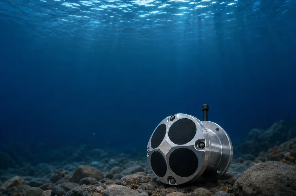
The Janus configuration works at both 20° and 30°, but the error rejection is more effective at narrower angles because the horizontal projection is larger relative to the vertical. A 5-beam system adds a center vertical beam — at 0° — for direct measurement of vertical velocity and water depth without relying on the coordinate transformation from angled beams. This is particularly valuable in applications where the vertical velocity signal is important (internal wave studies, sediment settling velocity) and the degraded vertical resolution of 20° angled beams is a liability. With a 5-beam system, you get the horizontal resolution advantage of 20° Janus beams plus a direct vertical measurement from the center beam — the best of both worlds, but at the cost of a more complex transducer head.
When to Prefer 20° (and Why Most Manufacturers Default to It)
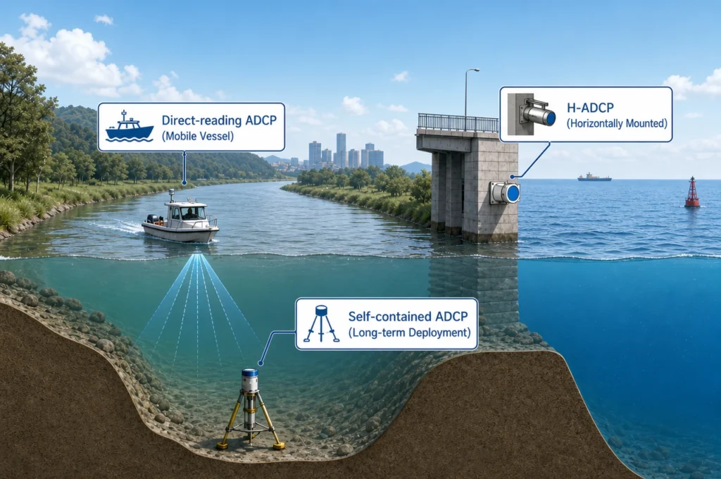
For the vast majority of ADCP applications — river discharge, coastal current monitoring, offshore engineering surveys, harbor navigation support — 20° is the correct beam angle. It provides superior horizontal velocity resolution, loses less of the water column to side-lobe interference, and is the standard against which most published ADCP data has been collected. 600kHz & 300kHz in Oceantek direct-reading ADCPs use a 20° beam angle for exactly these reasons.
Unless your application specifically requires better vertical velocity resolution — and you should be able to articulate why — 20° is the safe, well-understood choice. It is what most peer-reviewed studies assume, and it is what most data processing software expects.
When 30° Might Be Better
There are specific scenarios where a 30° beam angle is worth the trade-offs. If vertical velocity is the primary quantity you need — studying upwelling velocity, internal wave vertical displacement, convection in lakes, or sediment particle settling rates — the 13% improvement in vertical velocity resolution from a 30° beam angle may justify the loss of horizontal resolution and the increased side-lobe contamination zone.
Similarly, some specialized turbulence-measurement ADCPs use wider beam angles to increase the spatial separation between beam sample volumes at a given depth, which can improve the estimation of certain Reynolds stress components. These are research-grade instruments used by specialists who understand the trade-offs. For applied monitoring and survey work, you almost certainly want 20°.
Why 20° and 30°? A Brief History of Beam Angle Design
The ADCP industry converged on 20° and 30° for reasons that are part physics and part history. Early ADCPs in the 1980s and 1990s used 30° beams because the wider transducer spacing simplified the transducer-head machining and allowed larger individual transducer elements, which improved transmit power at a time when transducer efficiency was lower. As transducer manufacturing improved and signal processing became more sophisticated, the accuracy advantage of the narrower 20° beam angle became the dominant consideration, and the industry shifted.
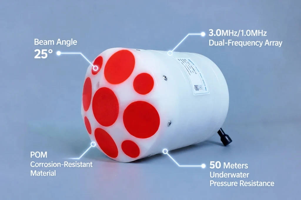
Today, 20° is the standard for general-purpose ADCPs, and 30° persists primarily in legacy product lines and a few specialized instruments. TRDI’s Workhorse series uses 20° beams. SonTek’s river discharge ADCPs use 25°, which splits the difference for reasons specific to their beam geometry. Nortek offers both angles depending on the instrument model. The convergence toward 20° is not a fad — it reflects the accumulated field experience that horizontal velocity resolution and side-lobe margin matter more to data quality than the modest improvement in vertical resolution from a wider angle.
Quantifying the Uncertainty: What Beam Angle Means for Your Error Bars
It is worth putting numbers to the uncertainty introduced by beam angle. The velocity uncertainty in an ADCP measurement comes from several sources — instrument noise, flow inhomogeneity between beams, Doppler spectral broadening — but beam geometry contributes a systematic component that is predictable.
For a standard 4-beam Janus ADCP, the uncertainty in the horizontal velocity components (u, v) scales approximately as 1/sin(θ), while the uncertainty in the vertical component (w) scales as 1/cos(θ). At 20°, the horizontal velocity standard deviation is roughly 15% lower than at 30° for the same acoustic conditions. For vertical velocity, the 30° beam gives about 7% lower uncertainty than 20°. This asymmetry — the horizontal improvement from narrowing the beam is larger than the vertical penalty — is another reason the industry has settled on narrower beam angles: most users care about horizontal velocity, and the physics favors narrower beams for that purpose.
The practical takeaway: if a datasheet claims velocity accuracy of ±0.25% of water velocity, that number is measured under controlled calibration conditions, not derived from beam geometry. The real uncertainty in a field deployment is higher and is influenced by beam angle, flow homogeneity, and instrument mounting stability. A narrower beam angle gives you a larger margin against real-world error sources, which is why it is the default in field instruments.
How to Use Beam Angle in Your Evaluation
When comparing ADCPs from different manufacturers, the beam angle is rarely the deciding factor — frequency, configuration, and price dominate. But it is a useful tiebreaker, and it is one of those specifications that rewards understanding over memorization.
If two instruments are otherwise equivalent and one uses 30° beams, ask the manufacturer why. There may be a good reason related to your specific application. More likely, you will discover that the decision was driven by a legacy transducer design rather than a deliberate optimization for your use case. In either case, you will be making the decision informed rather than defaulting to the specification you happened to see first.
For further reading on how beam angle interacts with frequency, cell size, and other ADCP parameters, see our complete ADCP parameter selection guide.