In this post
- Introduction:Oceantek 75k ADCP for Precision Current Measurement
- What Is the Oceantek ADCP-75-DR-PA4?
- Phased Array Technology: The Core Advantage
- Shipborne Underway Measurement: How It Works?
- Applications in Deep-Sea Large-Scale Detection
- Oceantek 75kHz ADCP vs. Competing Solutions
- Why Choose Oceantek for Your Deep-Sea Current Measurement Needs?
- Deployment Best Practices for Vessel-Mounted 75 kHz ADCP
- Frequently Asked Questions
- Conclusion: A New Benchmark for Accessible Deep-Sea Current Profiling
Introduction:Oceantek 75k ADCP for Precision Current Measurement
The deep ocean remains one of the least understood frontiers on Earth. For oceanographers, offshore engineers, and marine researchers, obtaining accurate, large-scale precision current measurements at depth has long been a formidable technical challenge. Traditional single-point current meters offer limited spatial coverage. Lowered ADCPs (LADCPs) provide profiles at discrete stations but cannot capture continuous spatial variability along a cruise track. Enter the Oceantek ADCP-75-DR-PA4 — a phased-array 75 kHz Acoustic Doppler Current Profiler purpose-built for shipborne underway deep-sea current measurement, delivering profiling ranges up to 650 meters with industry-leading accuracy.
This article provides a comprehensive technical review of the Oceantek 75kHz ADCP: how its phased-array architecture outperforms conventional piston-transducer designs, why 75 kHz strikes the optimal balance between range and resolution for deep-water profiling, real-world deployment scenarios from oceanographic cruises, and practical guidance for integrating this instrument into your research or operational workflow. Whether you’re planning a deep-water hydrographic survey, studying mesoscale eddy dynamics, or monitoring offshore infrastructure, this guide covers what you need to know.
1. What Is the Oceantek ADCP-75-DR-PA4?
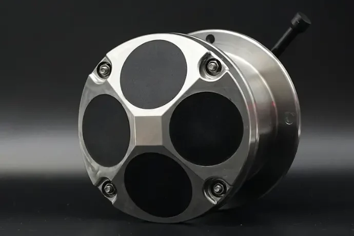
The Oceantek ADCP-75-DR-PA4 is a direct-reading, phased-array Acoustic Doppler Current Profiler operating at 75 kHz, designed and manufactured by Oceantek (偶信科技), a specialized Chinese oceanographic instrument company based in Hangzhou. The “DR” designation stands for Direct Reading — meaning the instrument transmits data in real time via cable (RS-232/RS-422 serial interface), with no internal battery limitation. The “PA4” denotes its 4-beam Janus phased-array transducer configuration.
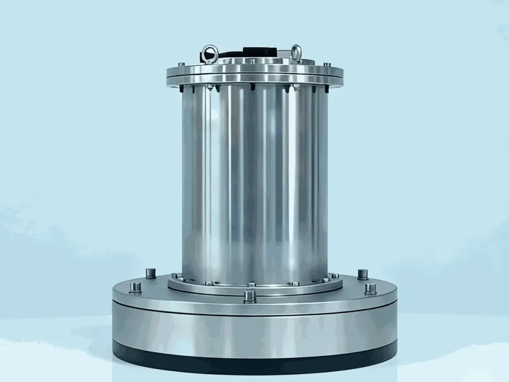
Figure 1 : Oceantek 75kHz ADCP : ADCP-75-DR-PA4
Unlike self-contained ADCPs that rely on internal batteries and memory for autonomous deployment, the direct-reading architecture makes the ADCP-75-DR-PA4 ideal for vessel-mounted, real-time current profiling. Power is supplied externally (20–50V DC), and data streams continuously to an onboard acquisition computer, enabling immediate quality control and adaptive survey planning — a critical advantage when operating in dynamic deep-sea environments.
Key Specifications at a Glance
| Parameter | Specification |
|---|---|
| Operating Frequency | 75 kHz |
| Water Profiling Range | 550 m (broadband) / 650 m (narrowband) |
| Bottom Tracking Range | 1,000 m |
| Velocity Accuracy | ±1.0% ±5 mm/s |
| Velocity Resolution | 1 mm/s |
| Velocity Range | ±5.0 m/s (default); ±10.0 m/s (maximum) |
| Beam Configuration | 4-beam Janus phased array, 30° beam angle |
| Beam Width | 3.5° |
| Depth Rating | 1,500 m |
| Number of Depth Cells | 1–255 (user-configurable) |
| Cell Size | 4–32 m (user-configurable) |
| Data Update Rate | 1 Hz (no bottom track); 0.5 Hz (with bottom track) |
| Housing Material | Titanium alloy |
| Communication | RS-232 or RS-422 |
| Power Supply | 20–50V DC, 5A |
| Operating Temperature | -5°C to 45°C |
| Integrated Sensors | Temperature (±0.1°C), Pressure (±0.25%), Attitude/Compass (0.2° roll/pitch, 0.8° heading RMS) |
| Heading Accuracy | ±2° |
2. Phased Array Technology: The Core Advantage
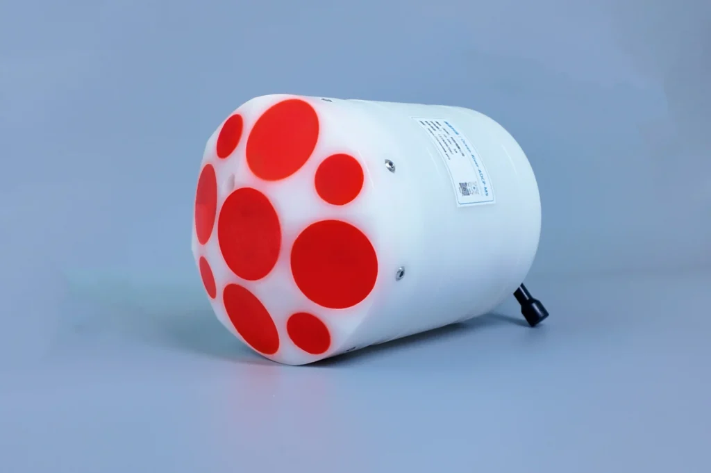
The most distinctive engineering feature of the ADCP-75-DR-PA4 is its phased-array transducer — a technology that fundamentally differentiates it from conventional piston-transducer ADCPs. Understanding this difference is essential for evaluating the instrument’s performance envelope.

Figure 2 : Phased Array Transducer of ADCP-75-DR-PA4
2.1 How Phased Array ADCPs Work
In a traditional piston-transducer ADCP, four discrete ceramic piston transducers are mounted in a Janus configuration — each pointed in a different direction at a fixed angle (typically 20°–30° from vertical). Each transducer mechanically steers its acoustic beam. While proven and widely adopted, this design has inherent limitations: each transducer requires its own housing aperture, the assembly is relatively bulky, and the physical beam angle is fixed at manufacture.
A phased-array ADCP replaces the four individual pistons with a single flat array of many small piezoelectric elements. By applying precisely controlled phase delays to the electrical signals driving each element, the array electronically steers the acoustic beams in four directions simultaneously — without any moving parts. This beam-forming is achieved entirely through digital signal processing (DSP).
2.2 Advantages of Phased Array for Deep-Water 75 kHz ADCP
- Compact form factor. A single flat array replaces four angled transducer heads, reducing the instrument’s physical size and weight. The titanium alloy housing of the ADCP-75-DR-PA4 is notably smaller than equivalent piston-type 75 kHz ADCPs — a practical advantage for vessel mounting, especially on smaller research vessels or USVs.
- Improved acoustic performance. The phased array’s larger effective aperture produces a narrower beam width (3.5°) compared to piston transducers at the same frequency. A narrower beam reduces acoustic side-lobe interference — a critical factor when profiling close to the seabed, where side-lobe contamination can corrupt velocity data in the bottom 10–15% of the water column.
- Electronic beam angle flexibility. While the ADCP-75-DR-PA4 operates at a fixed 30° beam angle, the phased-array architecture theoretically allows beam-angle adjustment through firmware — a capability not possible with mechanically fixed piston transducers.
- Higher reliability. No moving parts and fewer mechanical interfaces mean fewer failure points over years of deployment in corrosive marine environments.
- Lower flow disturbance. The flat array face creates less hydrodynamic disturbance around the transducer head, reducing flow-induced bias in near-transducer velocity measurements.
Technical Insight: Phased-array ADCPs first entered oceanographic use through Teledyne RDI’s Ocean Surveyor series. The Oceantek ADCP-75-DR-PA4 represents an independent, offering comparable or superior specifications at a competitive price point — an important development for research programs seeking alternatives to established Western manufacturers.
3. Shipborne Underway Measurement: How It Works?
The defining operational mode of the ADCP-75-DR-PA4 is vessel-mounted underway current profiling — measuring ocean current velocity continuously along a ship’s track without stopping on station. This capability transforms a research cruise from collecting isolated vertical profiles into generating continuous, spatially-resolved transects of the 3D current field.
3.1 The Measurement Principle
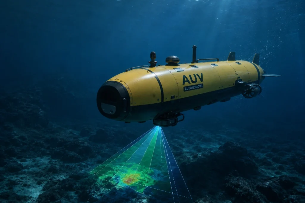
When mounted on a vessel’s hull (or deployed through a moon pool/sea chest), the ADCP transmits acoustic pulses downward along four beams. Sound is backscattered by suspended particulate matter, plankton, and fine sediment in the water column — collectively termed “scatterers.” The Doppler frequency shift between transmitted and received signals yields the relative velocity between the instrument and each scattering layer.
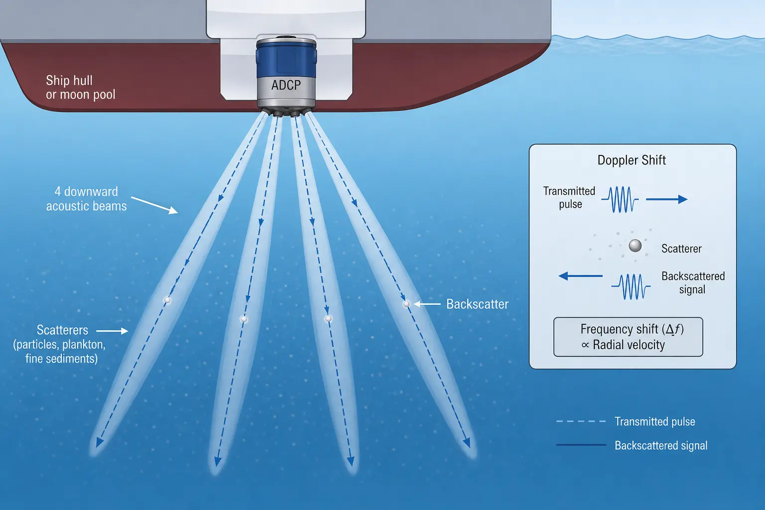
Figure 3 : Measurement Principle of 4-beam ADCP
Three critical corrections are then applied in real time:
- Vessel motion compensation. The integrated attitude sensor (roll/pitch/heading) and external GPS input correct for ship heave, pitch, roll, and course changes.
- Coordinate transformation. Beam-coordinate velocities (along each of the four acoustic axes) are converted to Earth-coordinate (East, North, Up) velocities using the Janus transformation matrix.
- Vessel speed removal. The ship’s speed-over-ground (from GPS) is subtracted from the measured velocities to isolate the absolute water velocity.
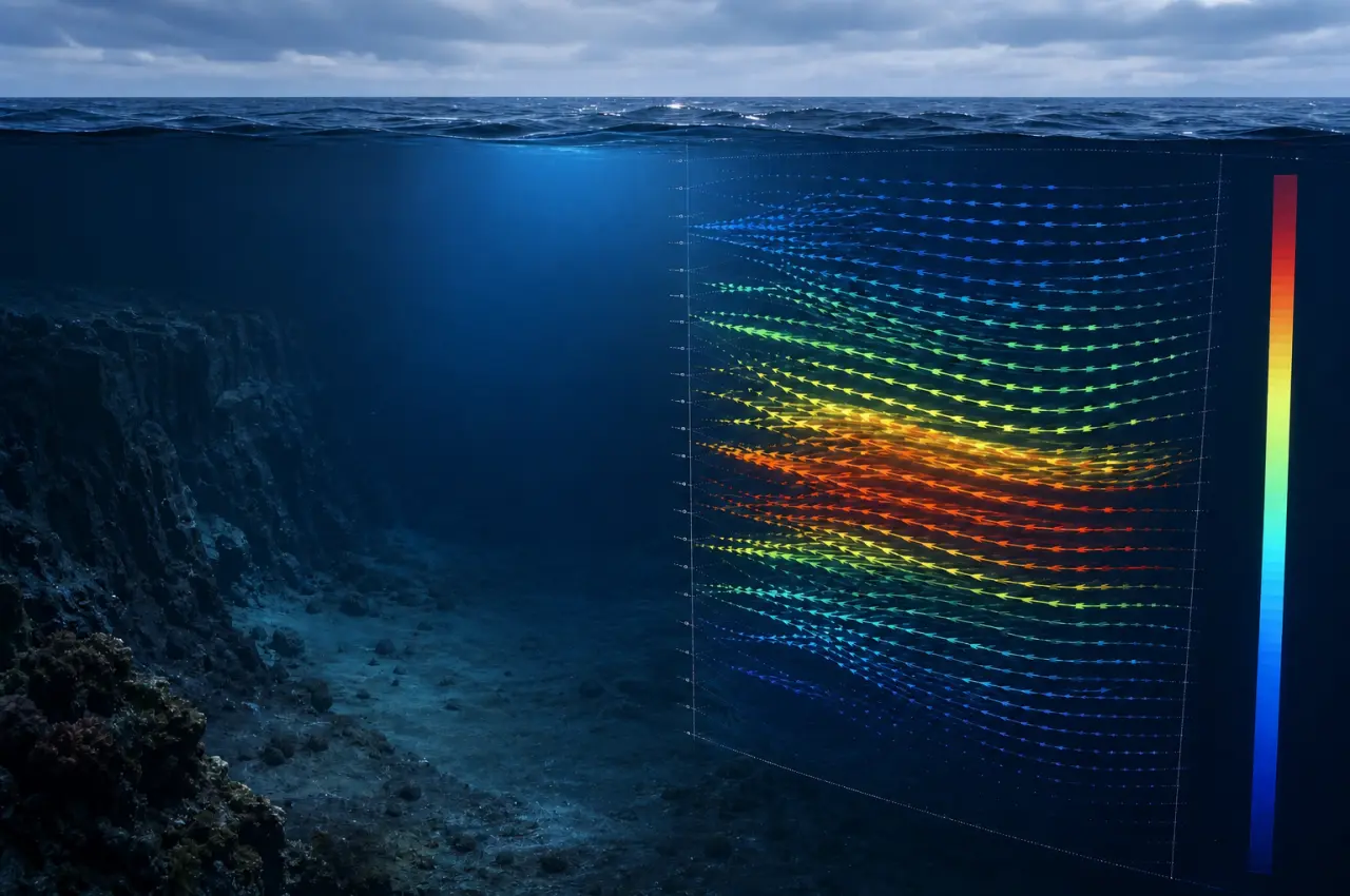
The result: a vertical profile of horizontal current velocity at every ensemble — typically every 1–2 seconds — building a continuous cross-section of ocean currents along hundreds or thousands of kilometers of cruise track.
3.2 Why 75 kHz for Deep-Water Underway Profiling?
The choice of acoustic frequency involves a fundamental trade-off in underwater acoustics: lower frequency → longer range, but coarser resolution. At 75 kHz, the ADCP-75-DR-PA4 occupies a sweet spot in the ADCP frequency spectrum:
| Frequency | Typical Profiling Range | Typical Application |
|---|---|---|
| 600 kHz | 50–80 m | Coastal/estuarine surveys, high-resolution boundary layer studies |
| 300 kHz | 100–150 m | Shelf sea surveys, offshore wind resource assessment |
| 150 kHz | 250–350 m | Upper-ocean mesoscale studies, continental slope surveys |
| 75 kHz | 550–650 m | Deep-water basin-scale surveys, boundary current studies, deep convection monitoring |
At 75 kHz, the ADCP-75-DR-PA4 reaches depths of 550 m in broadband mode and 650 m in narrowband mode — sufficient to capture the permanent thermocline, the core of most boundary currents, and the depth range where mesoscale eddy kinetic energy is concentrated. The 38 kHz alternative, while offering deeper penetration (up to ~1,600 m), requires a substantially larger transducer that cannot be installed on most vessels. The 75 kHz phased-array design thus represents the maximum profiling depth achievable in a practical, vessel-mountable form factor.
4. Applications in Deep-Sea Large-Scale Detection
The Oceantek 75kHz ADCP excels in scenarios where wide-area, deep-water current mapping is the primary objective. Drawing on peer-reviewed deployments of 75 kHz vessel-mounted ADCPs in international oceanographic programs, the instrument is suited for the following application domains:
4.1 Mesoscale Eddy and Front Surveys
Mesoscale eddies (50–200 km diameter) and oceanic fronts concentrate much of the ocean’s kinetic energy. Their vertical structure often extends to 500–800 m depth — well within the ADCP-75-DR-PA4’s profiling envelope. Vessel-mounted 75 kHz ADCPs have been used extensively to map the 3D velocity structure of Agulhas rings in the South Atlantic, Gulf Stream meanders in the North Atlantic, and the Great Whirl–Socotra Gyre system in the Indian Ocean. Continuous underway profiling reveals the tilted vortex structure, subsurface intensification, and asymmetric velocity distribution that characterize these features.
4.2 Western Boundary Current Studies
Western boundary currents — the Gulf Stream, Kuroshio, Agulhas, and Brazil currents — transport vast volumes of heat and salt. Their cores typically lie at 300–600 m depth. The ADCP-75-DR-PA4’s 650 m range (narrowband) captures the full depth extent of these currents, including the undercurrents and recirculation cells often present beneath the surface-intensified flow. Repeated transects with this instrument enable accurate volume transport calculations essential for climate-scale ocean monitoring.
4.3 Deep Convection and Water Mass Formation
In regions like the Greenland Sea, Labrador Sea, and Gulf of Lions, winter cooling drives deep convective overturning that forms intermediate and deep water masses. 75 kHz ADCPs deployed during research cruises have documented convective plumes reaching 500–800 m depth, with vertical velocities of several cm/s — measurements essential for understanding the thermohaline circulation. The ADCP-75-DR-PA4’s narrow 3.5° beam width is particularly advantageous here, reducing side-lobe contamination that could otherwise mask the weak vertical velocity signal.
4.4 Offshore Energy and Infrastructure
For offshore wind farm site assessment, subsea cable route surveys, and oil/gas platform operations in deep water (500–1,500 m), understanding the current regime throughout the water column is critical for engineering design and operational safety. The ADCP-75-DR-PA4’s direct-reading capability allows real-time current monitoring during ROV operations, drilling campaigns, and installation activities, while its titanium housing ensures corrosion resistance during extended vessel-mounted deployments.
4.5 Under-Ice and Polar Oceanography
During the MOSAiC expedition (2019–2020), a 75 kHz phased-array ADCP was deployed downward through Arctic sea ice to measure upper-ocean currents continuously beneath the drifting ice pack. The ADCP-75-DR-PA4’s compact titanium housing and phased-array architecture make it compatible with deployment through ice holes and on icebreaker hulls — applications where the smaller transducer footprint directly reduces installation complexity.
5. Oceantek 75kHz ADCP vs. Competing Solutions
To provide context for procurement decisions, the following table compares the Oceantek ADCP-75-DR-PA4 against broadly equivalent instruments from other manufacturers. Note that direct specification comparisons are approximate, as manufacturers report performance under different assumptions.
| Feature | Oceantek ADCP-75-DR-PA4 | Teledyne RDI Workhorse 75 kHz | Nortek Signature 75 kHz |
|---|---|---|---|
| Technology | Phased array | Phased array | 3 transducers |
| Profiling Range | 550–650 m | >700 m | >600m |
| Depth Rating | 1,500 m | 1,500 m | 1,500 m |
| Bottom Tracking Range | 1000m | 950m | >600m |
| Velocity Accuracy | ±1.0% ±5 mm/s | ±1.0% ±5 mm/s | ±1.0% ±5 mm/s |
| Housing Material | Titanium alloy | Aluminum / optional titanium | POM with titanium fasteners |
| Price (approx.) | $$ | $$$$ | $$$ |
| Patent / IP | Chinese patent (Oceantek) | U.S. patents (Teledyne) | Norwegian/EU patents |
⚡ Key Takeaway: The Oceantek ADCP-75-DR-PA4 delivers phased-array performance competitive with Teledyne RDI’s industry-standard Ocean Surveyor, at approximately 25–40% lower cost. The primary trade-off is a marginally shallower depth rating (1,500 m vs. some competitors’ deeper ratings) — though 1,500 m covers the vast majority of vessel-mounted deployment scenarios. For organizations constrained by budget or facing export-control restrictions on Western oceanographic instruments, the Oceantek ADCP represents a compelling alternative.
6. Why Choose Oceantek for Your Deep-Sea Current Measurement Needs?
6.1 Independent Technology Development
Oceantek holds an independent Chinese invention patent (ZL 2024 1 0471866.4) for its phased-array ADCP technology. This is not a licensed or derivative design — it is an in-house engineered solution that has undergone China’s rigorous patent examination process. For international research collaborations, this means no dependence on any single Western manufacturer’s supply chain, reducing procurement risk in an era of evolving export control regimes.
6.2 Titanium Alloy Housing: Built for the Marine Environment
The ADCP-75-DR-PA4’s titanium alloy housing is a premium feature typically found only on high-end or custom oceanographic instruments. Titanium offers:
- Exceptional corrosion resistance in seawater — far superior to aluminum or stainless steel — eliminating the need for sacrificial anodes
- High strength-to-weight ratio — the instrument is lighter than equivalent aluminum-housed ADCPs, reducing the mechanical load on vessel mounting fixtures
- Biofouling resistance — titanium’s surface properties discourage marine growth, maintaining acoustic transparency over multi-month deployments
- Non-magnetic properties — titanium does not interfere with the internal compass, preserving heading accuracy
6.3 Direct-Reading Architecture: Real-Time Data, Zero Battery Constraints
Unlike self-contained ADCPs limited by battery capacity and internal memory, the DR (Direct Reading) configuration delivers unlimited deployment endurance — as long as vessel power is available, the ADCP operates. Real-time data streaming enables:
- Immediate data quality assessment — identify and correct issues (e.g., insufficient scatterers, acoustic interference) while still on site
- Adaptive survey design — adjust cruise track or station duration based on observed current features
- Integration with ship’s data network — feed current data to other instruments (multibeam echosounder, CTD, meteorological sensors) for synchronized data logging
6.4 Competitive Pricing and Accessible Support
At approximately ¥499,800 (~$68,500 USD) for the direct-reading version, the Oceantek 75kHz ADCP significantly undercuts equivalent Western instruments while delivering comparable specifications. Oceantek provides direct manufacturer support through cecilia@oceantek.pro, offering shorter response times and more flexible customization than many larger multinational instrument manufacturers.
7. Deployment Best Practices for Vessel-Mounted 75 kHz ADCP
Drawing on established protocols from the oceanographic community — including the EMSO ADCP best practices presented at OCEANS 2025 (Brest) and the OSADCP processing framework — the following recommendations maximize data quality from the ADCP-75-DR-PA4:
7.1 Pre-Deployment Calibration
- Compass calibration. Perform a full 360° compass swing calibration after installation and before each cruise. EMSO studies have shown that uncorrected compass errors (up to 10° from magnetic interference) can bias current transports by 10–16%.
- Water-track calibration. Conduct a dedicated calibration transect (reciprocal course over ~2 hours in >200 m water depth) to determine transducer misalignment angle (typical precision: ±0.5–0.7°) and scaling factor.
- Time synchronization. Ensure GPS NMEA input is synchronized with the ship’s master clock to avoid timing offsets that degrade vessel motion correction.
7.2 Real-Time Monitoring
- Monitor echo intensity. Declining echo intensity with depth indicates scatterer concentration. If the signal-to-noise ratio drops below ~3 dB, consider reducing cell size or switching to narrowband mode for extended range.
- Track percent-good. Flag ensembles where percent-good falls below 25% (SeaDataNet standard threshold).
- Watch for side-lobe interference. Velocity data in the deepest 10–15% of the profile (nearest the seabed) should be discarded or treated with caution due to side-lobe contamination from bottom reflection.
7.3 Post-Processing
- Apply sound speed correction. Use in-situ CTD profiles or climatological sound speed data to correct for refraction effects on beam geometry.
- Remove acoustic interference. Flag and remove data contaminated by interference from other acoustic instruments (echosounders, sub-bottom profilers) operating simultaneously.
- Validate against independent measurements. Cross-check against lowered ADCP (LADCP) profiles or geostrophic shear computed from CTD transects to quantify residual errors.
8. Frequently Asked Questions
What is the maximum profiling depth of the Oceantek 75kHz ADCP?
The ADCP-75-DR-PA4 achieves 550 m in broadband mode and 650 m in narrowband mode. Actual range depends on water column scatterer abundance, which varies regionally and seasonally. In scattering-rich waters (e.g., coastal upwelling zones, spring bloom conditions), maximum range may exceed 650 m; in oligotrophic open-ocean gyres, range may be reduced.
Can the Oceantek 75kHz ADCP be used on unmanned surface vessels (USVs)?
Yes. The ADCP-75-DR-PA4’s compact form factor, titanium housing, and low power consumption (20–50V DC, 5A peak) make it well-suited for integration on medium-to-large USVs. The direct-reading interface transmits data in real time via the USV’s communication link — a configuration successfully demonstrated in the Gulf of Mexico by the SeaTrac USV with Sonardyne ADCPs in 2024–2025.
What is the difference between direct-reading (DR) and self-contained ADCPs?
Direct-reading ADCPs (like the ADCP-75-DR-PA4) transmit data via cable in real time and require external power — ideal for vessel-mounted or cabled observatory deployments. Self-contained ADCPs operate autonomously on internal batteries with onboard data storage, suitable for mooring or seabed-frame deployments lasting weeks to months. Oceantek also offers a self-contained version of the 75 kHz ADCP for autonomous applications.
How does the phased-array design affect data quality compared to piston transducers?
The phased array’s narrower 3.5° beam width reduces acoustic side-lobe energy, which directly improves data quality in two ways: (1) reduced side-lobe contamination near the seabed — the “clean” portion of the profile extends closer to the bottom; and (2) lower sensitivity to surface reflection in rough sea states. Additionally, the phased array’s larger effective aperture improves signal-to-noise ratio at equivalent transmit power.
What after-sales support does Oceantek provide?
Oceantek offers direct manufacturer support including pre-deployment calibration, technical consultation, firmware updates, and repair services. Contact sales@oceanadcp.com for specific support inquiries. Oceantek, as the authorized distributor, also provides localized sales and technical support.
9. Conclusion: A New Benchmark for Accessible Deep-Sea Current Profiling
The Oceantek ADCP-75-DR-PA4 represents a significant milestone in the democratization of deep-sea oceanographic instrumentation. By delivering phased-array performance — 650 m profiling range, 3.5° beam width, titanium alloy construction, and ±1% velocity accuracy — at a price point 25–40% below established competitors, Oceantek has created a compelling option for research institutions, offshore operators, and survey companies seeking high-quality current measurement capability without the budgetary or export-control constraints of traditional Western suppliers.
The instrument’s direct-reading architecture makes it particularly well-suited to vessel-mounted underway surveys — the workhorse mode of oceanographic current measurement — while the independent Chinese patent (ZL 2024 1 0471866.4) underscores the seriousness of Oceantek’s engineering investment. For any organization planning deep-water current measurement campaigns in the 500–1,500 m depth range, the ADCP-75-DR-PA4 merits serious evaluation alongside instruments from Teledyne RDI and Nortek.
As ocean science enters an era of increasing data demand — from climate model validation and offshore renewable energy development to deep-sea mining environmental impact assessment — affordable, reliable, and accurate current measurement has never been more critical. The Oceantek 75kHz ADCP is positioned to play a central role in meeting that demand.
Ready to Deploy the Oceantek 75kHz ADCP for Your Next Survey?
Contact Oceantek today for a detailed quotation, technical consultation, or to schedule a demonstration.View Product Details & Request Quote →
Or email us directly: sales@oceanadcp.com