I. Test Background
At present, high-precision ADCP equipment in China mainly relies on imports. In particular, ADCP products from the U.S. company TRDI account for the largest import volume and dominate most of the domestic market. To change this passive situation and realize the domestic substitution of high-precision ADCP, this comparative test is carried out.
After systematic research, the independently developed and manufactured ADCP of our company, model OCEAN-300K, has comprehensive performance comparable to the TRDI Workhorse series ADCP. Therefore, a comparative test is conducted between the OCEAN-300K and Workhorse Sentinel ADCP-300K. The test consists of two parts: underway measurement comparison and static bottom-mounted measurement comparison. By comparing actual measurement results, this test aims to verify that the high-precision ADCP of the OCEAN series can replace imported high-precision ADCP equipment.
II. Test Overview
A comparative measurement is carried out between the domestic ADCP (OCEAN-300K) and the imported Workhorse Sentinel ADCP-300K. The test is divided into two categories: bottom-mounted static test and underway dynamic test. Under the same parameter configuration and application environment, multi-dimensional comparison of current measurement results is performed. It is defined that the overall error within 2% indicates basically consistent performance.
2.1 Test Objectives
To verify that the current measurement performance of the domestic OCEAN-300K ADCP is basically consistent with that of the imported Workhorse Sentinel ADCP-300K in both static bottom-mounted mode and underway mode, with the relative deviation of measured current velocity less than 2%.
2.2 Test Duration
March 21, 2023 to March 23, 2023, lasting for 3 days.
2.3 Test Location
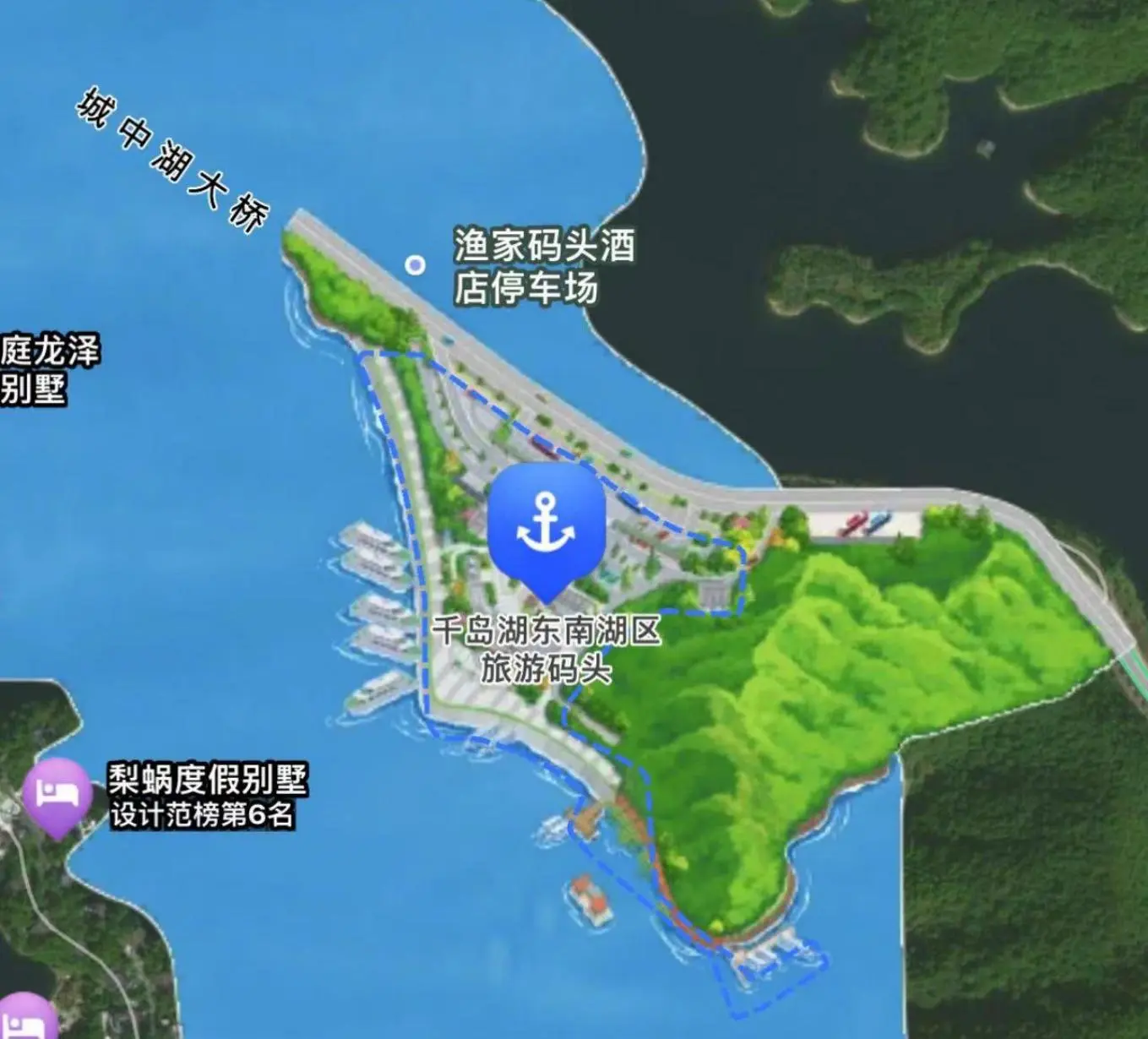
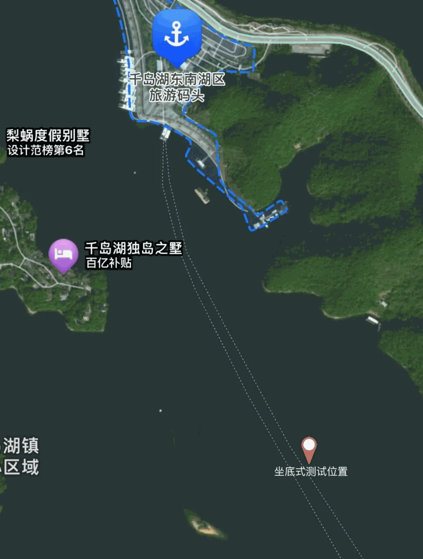
Southeast Lake Area, Qiandaohu Town, Chun’an County
Figure 2.3 Location Map of Qiandaohu Southeast Lake Wharf
2.4 Test Equipment
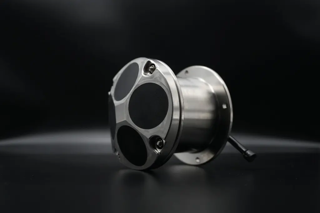
- One set of OCEAN-300K
- One set of Workhorse Sentinel ADCP-300K
- One set of GPS
- Two sets of mobile batteries
2.5 Test Methods
- Bottom-mounted test
- Underway navigation test
III. Test Content
The comparative test of OCEAN-300K and Workhorse Sentinel ADCP-300K includes two test modes: bottom-mounted test and underway navigation test.
In the bottom-mounted test, two devices were installed on a support frame for alternate transmitting and comparative measurement.
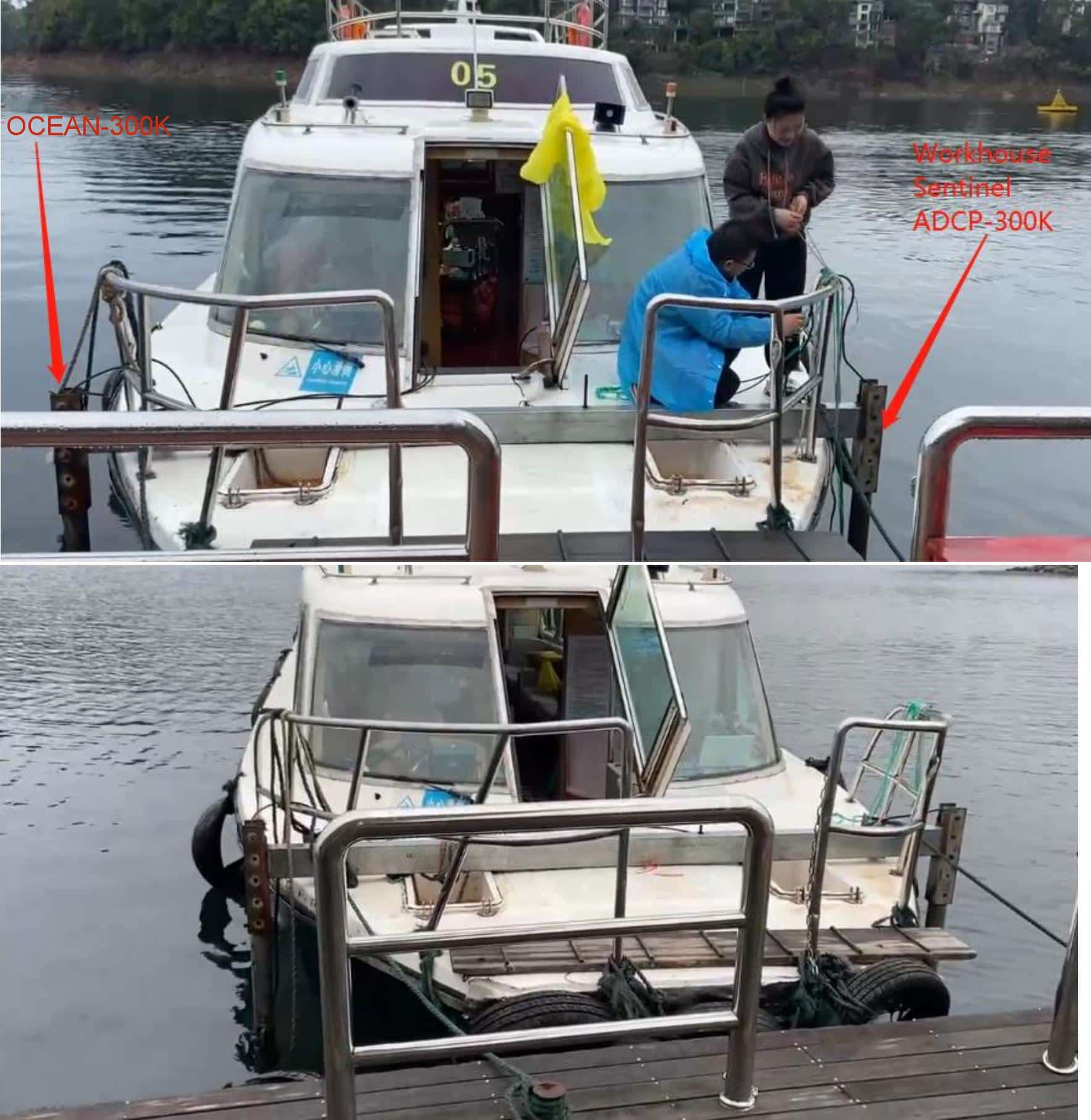
In the underway navigation test, OCEAN-300K was mounted on the starboard side of the vessel, while Workhorse Sentinel ADCP-300K was installed on the port side, with alternate transmitting adopted for comparison as well.
3.1 Bottom-mounted Comparative Test
3.1.1 Test Procedure
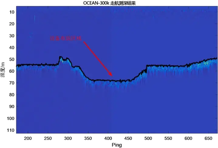
The water depth of the static test area is about 70 meters. The deployment area was confirmed after lake sweeping conducted by OCEAN-300K. The lake sweeping results are shown in the figure below.
Figure 3.1.1 Equipment Deployment Area Map
Preparation of the OCEAN-300K and Workhorse Sentinel ADCP-300K equipment and materials commenced at 10:30 a.m. on March 21, 2023. To ensure the units start operating after being deployed underwater, the startup time of the OCEAN-300K was scheduled for 1.5 hours later, with an official activation at 12:00, which reserved sufficient time for bracket installation and vessel transit to the test area.
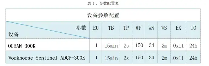
An alternating operation mode was adopted for this test, with each device operating once every five minutes. The OCEAN-300K was set to start at 12:00, while the Workhorse Sentinel ADCP-300K was scheduled to start at 12:07. The first data output of both devices was determined by multiplying the calculation cycle (2 seconds) by the current measurement ping count (150), resulting in a five‑minute interval. All subsequent outputs followed the set operating interval TB of 15 minutes. The continuous operating duration for both instruments was no less than 24 hours.
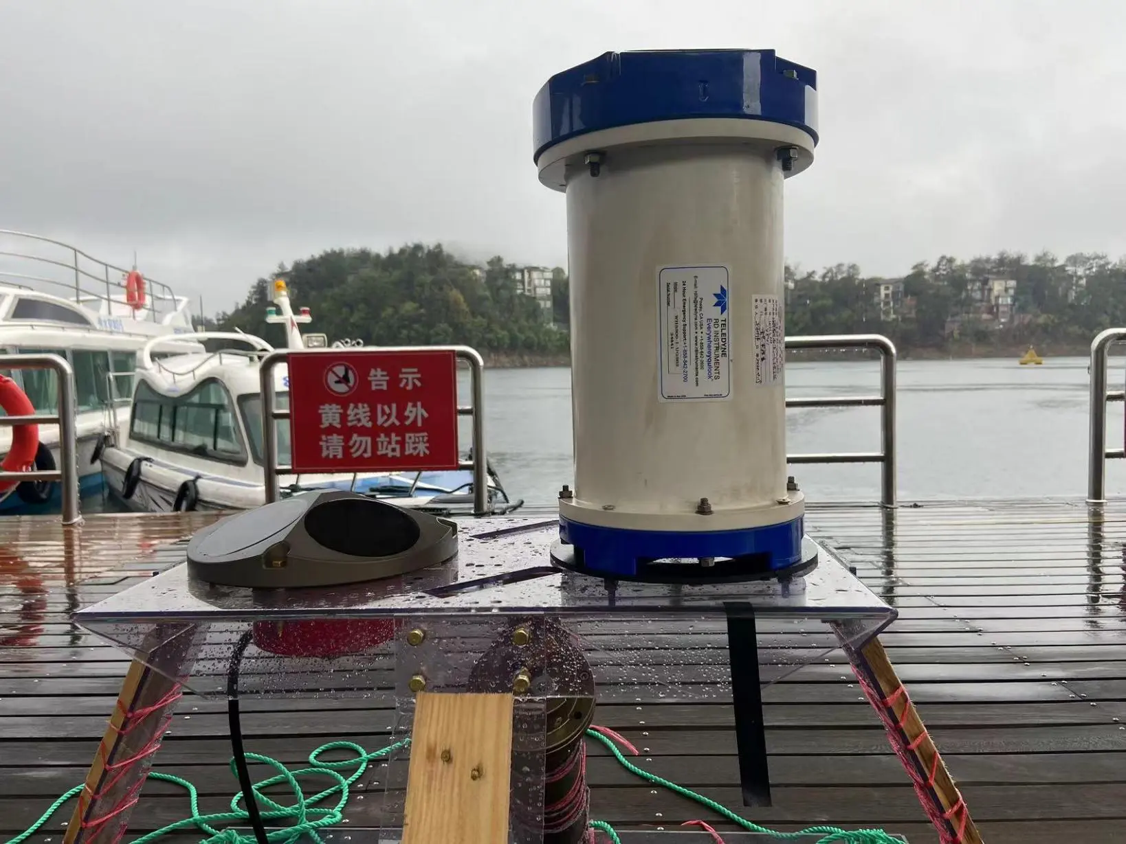
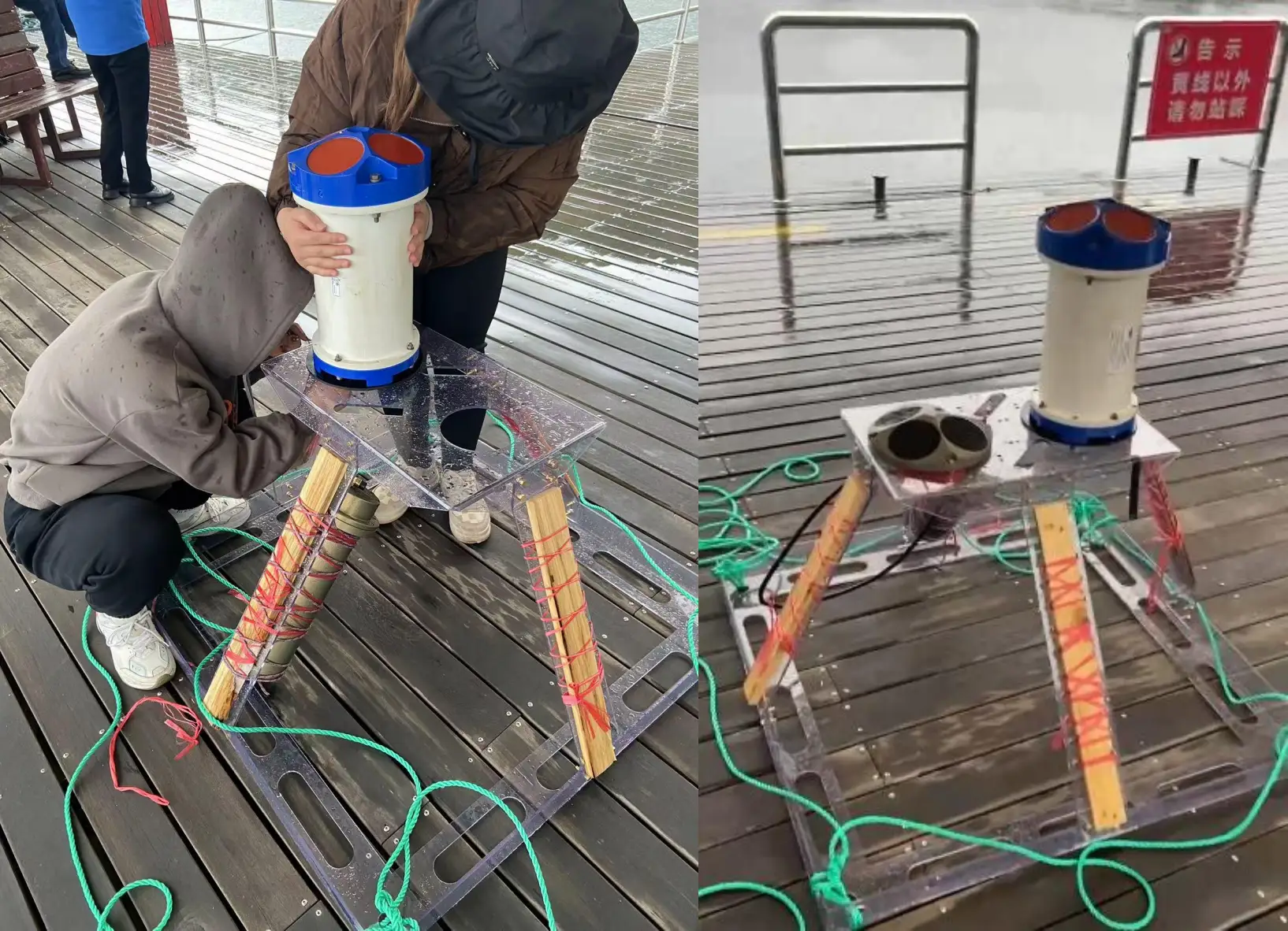
Pre-installation materials: batteries, cables, OCEAN-300K unit, Workhorse Sentinel ADCP-300K unit, copper studs, nuts, rubber gaskets, Kevlar ropes, buoys, and bottom-mounted support frame.
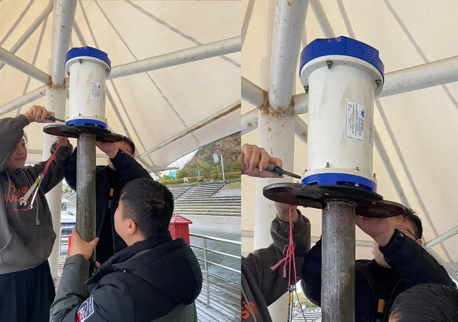
Mounting holes were pre-drilled for the installation of the OCEAN-300K and Workhorse Sentinel ADCP-300K. Rubber gaskets were aligned with the mounting holes and secured using matched-length studs. Two nuts were fitted on each stud to prevent loosening and equipment detachment. Battery compartments were firmly fastened in place with Kevlar ropes, and the OCEAN-300K was connected to the power battery via cables. The forward orientation of both ADCPs was strictly unified. After full assembly, ropes at the four corners of the support frame were tightly bound and leveled to avoid tipping during deployment on the lakebed.
Figure 3.1.2 Equipment Installation Process at the Wharf
The on-site preparation at the wharf was completed at 11:23, after which the entire support frame was loaded onto the boat and transported to the test area.
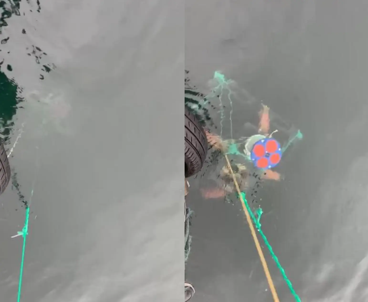
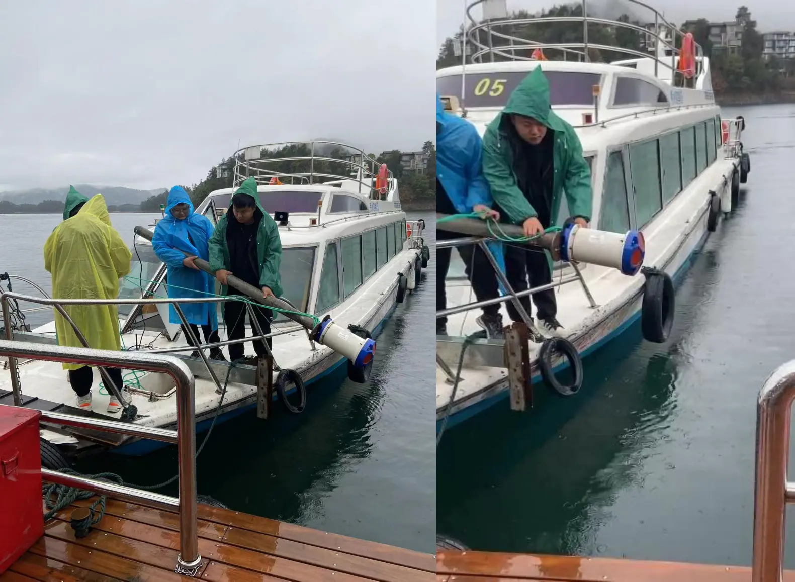
The vessel arrived at the test area at 11:40, and the equipment was then deployed into the lake.
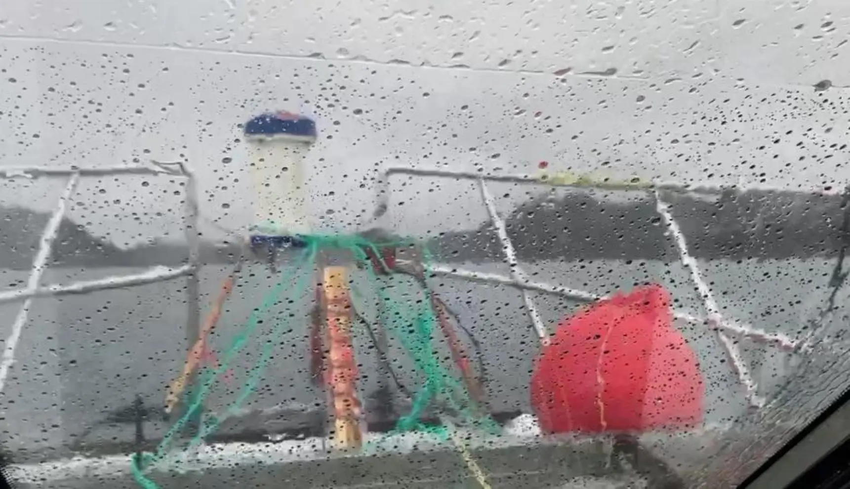
Figure 3.1.5 Successful Equipment Deployment
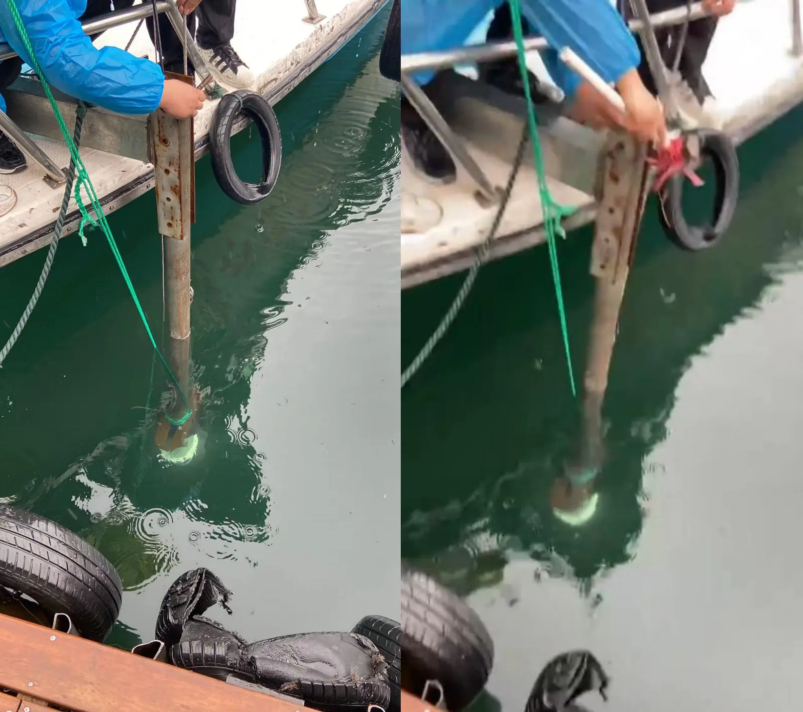
Once the equipment settled on the lakebed, the buoys were released into the lake. The ropes of the support frame were connected to the buoys, enabling quick location and recovery of the equipment by identifying the buoys during retrieval.
Figure 3.1.6 Location Diagram of Buoys (Equipment)
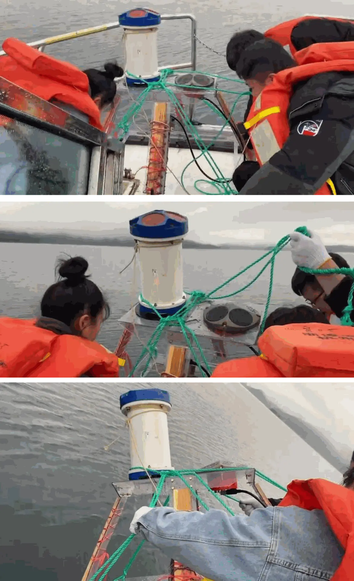
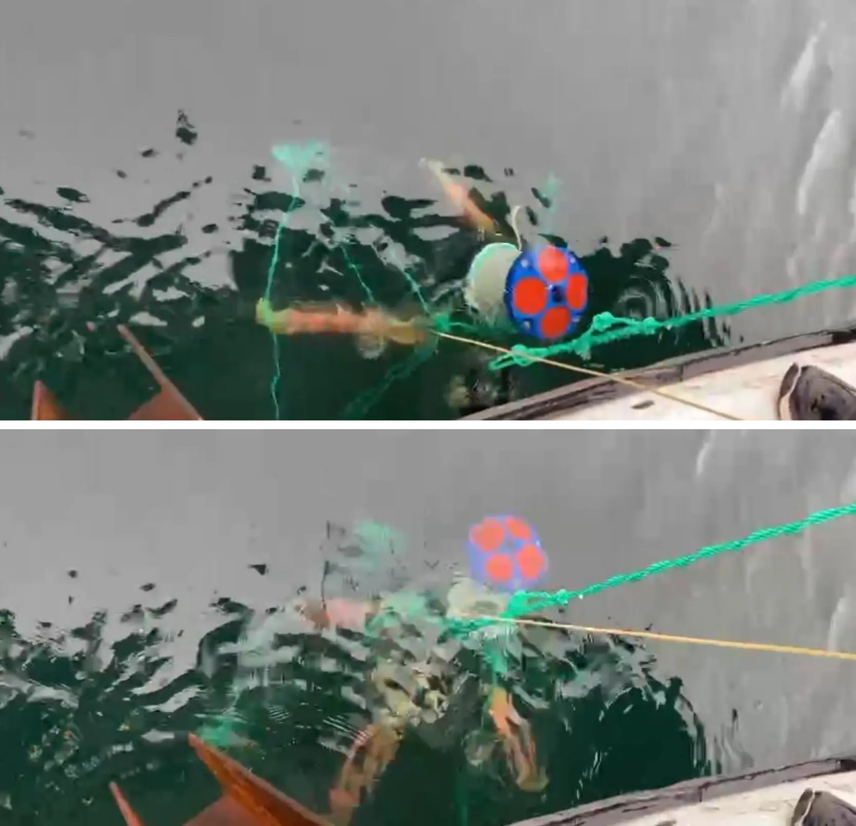
At 13:00 on the afternoon of March 21, 2023, personnel headed to the test site to recover the equipment.
Figure 3.1.7 Location Diagram of Recovered Buoys (Equipment)
Figure 3.1.8 Equipment Recovery Process Diagram
Notes: Parameter Configuration
OCEAN-300K Start Time (TG): 12:00:00, March 21, 2023
Workhorse Sentinel ADCP-300K Start Time (TG): 12:07:00, March 21, 2023
Definitions:
EU: Sets the equipment orientation (1 – upward, 0 – downward);
TB: Sets the interval between pings, namely the operating period;
TP: Sets the transmission interval between pings, namely the transmit period;
WP: Sets the ping count for current measurement;
WN: Sets the number of measurement layers;
WS: Sets the layer thickness;
EX: Sets the coordinate system; 0x11 represents the geodetic coordinate system;
TO: Sets the operating duration (used in conjunction with TG);
TG: Sets the start time of the equipment.
3.1.2 Test Results
Both the OCEAN-300K and Workhorse Sentinel 300K ADCPs adopt the PD0 output format. To improve the accuracy of comparison results, Matlab was used to unpack, compare and analyze the stored data from the two devices respectively.
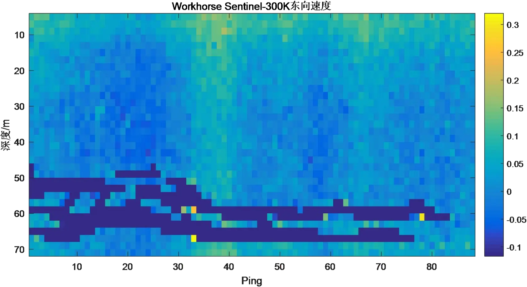
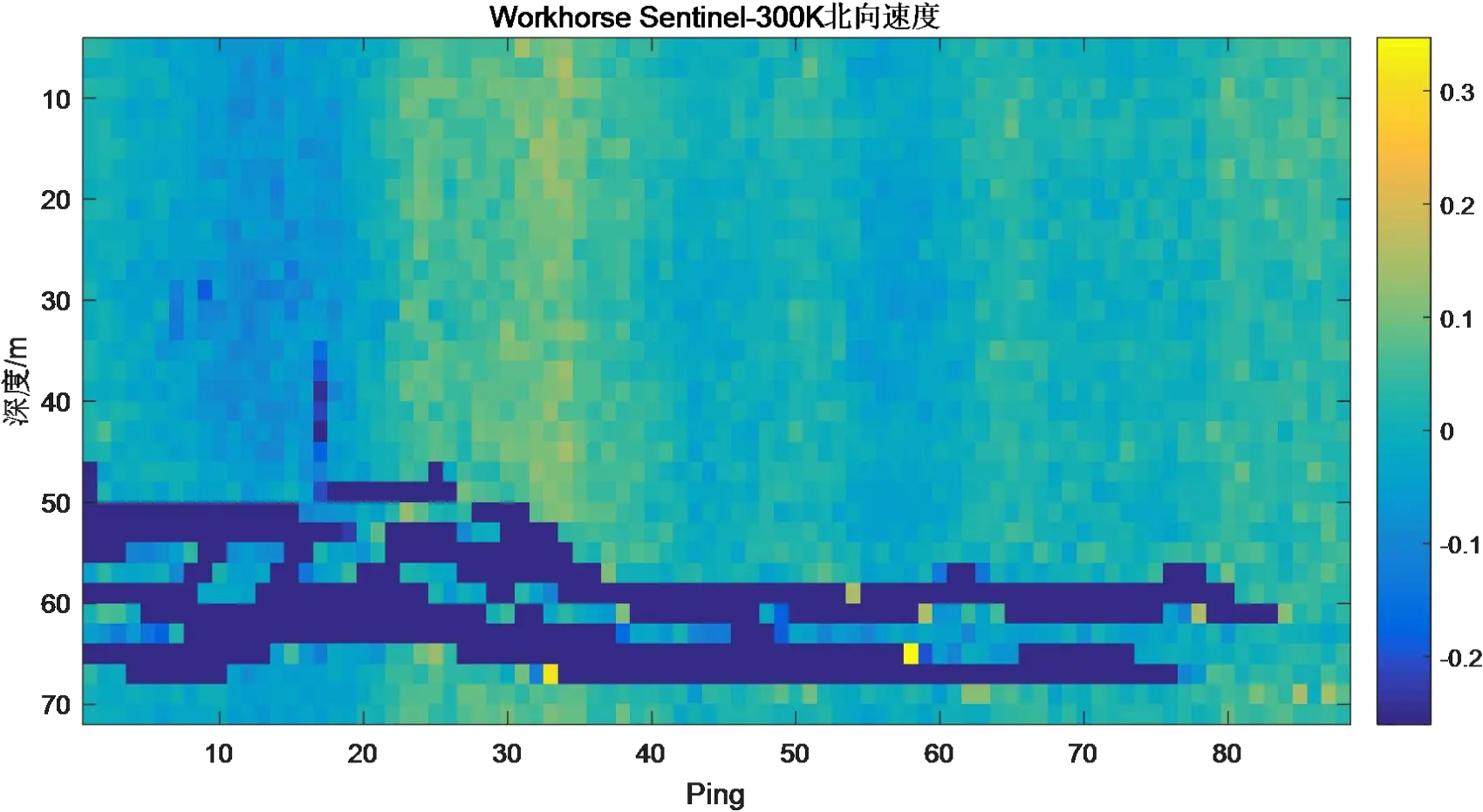
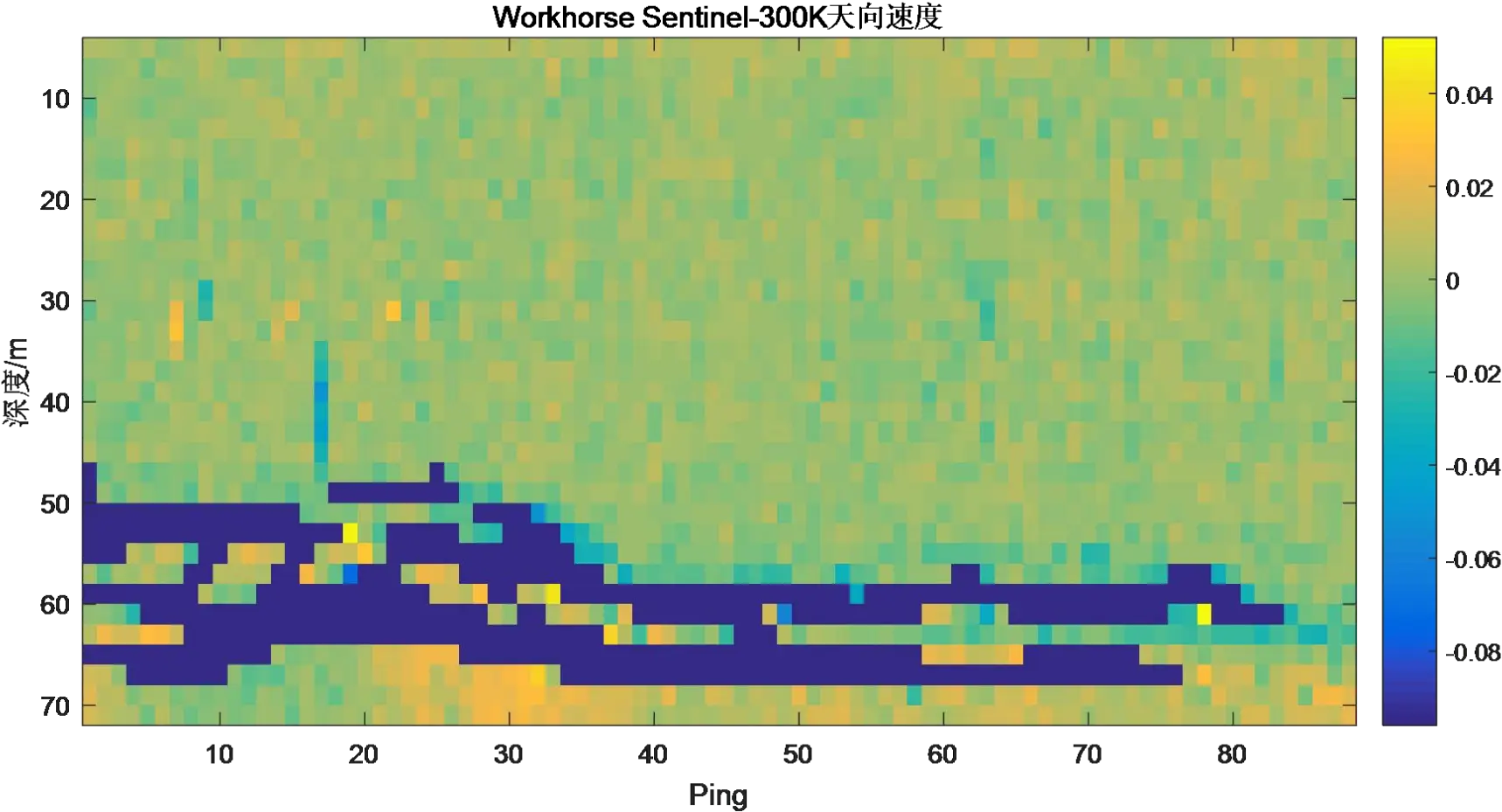
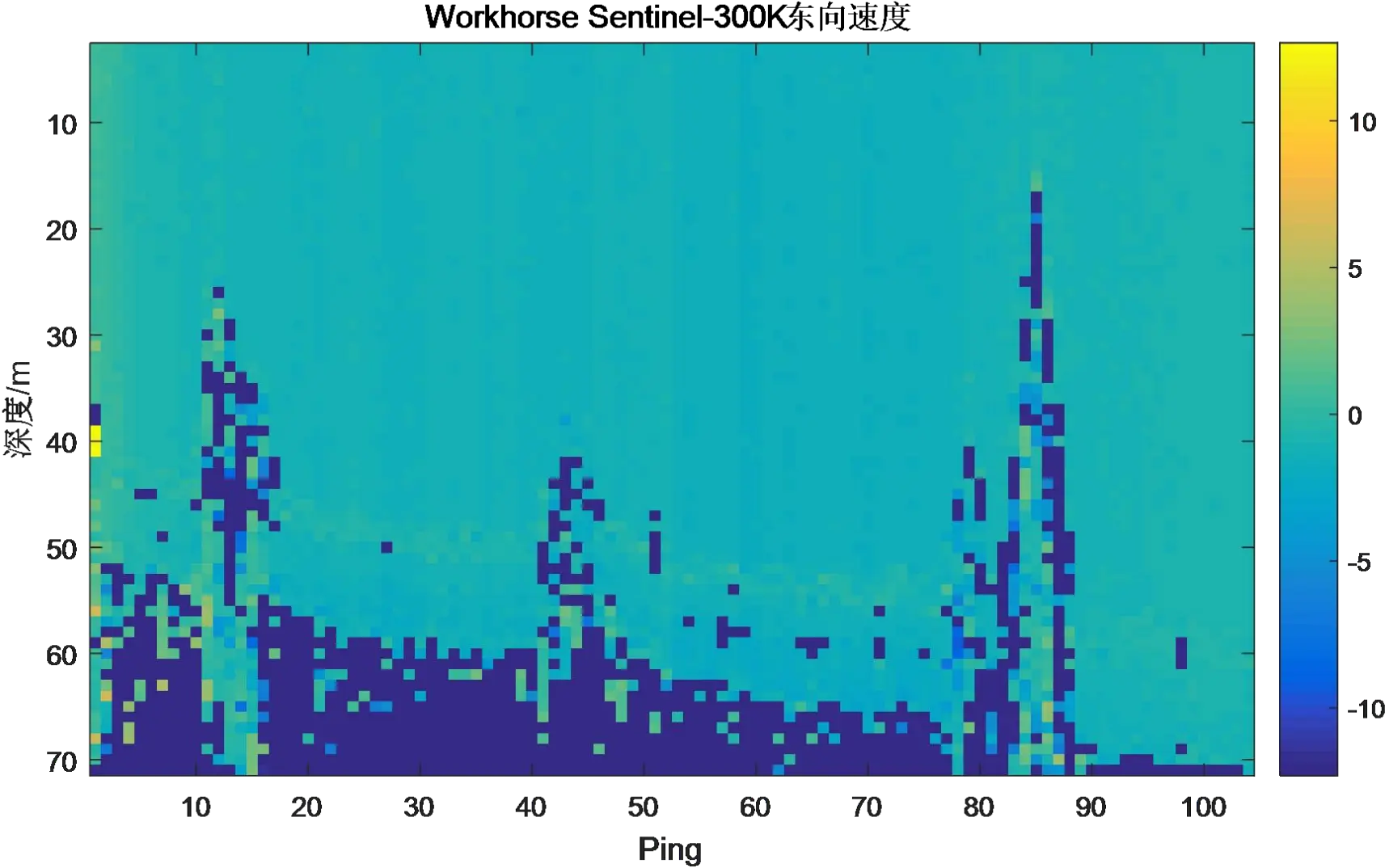
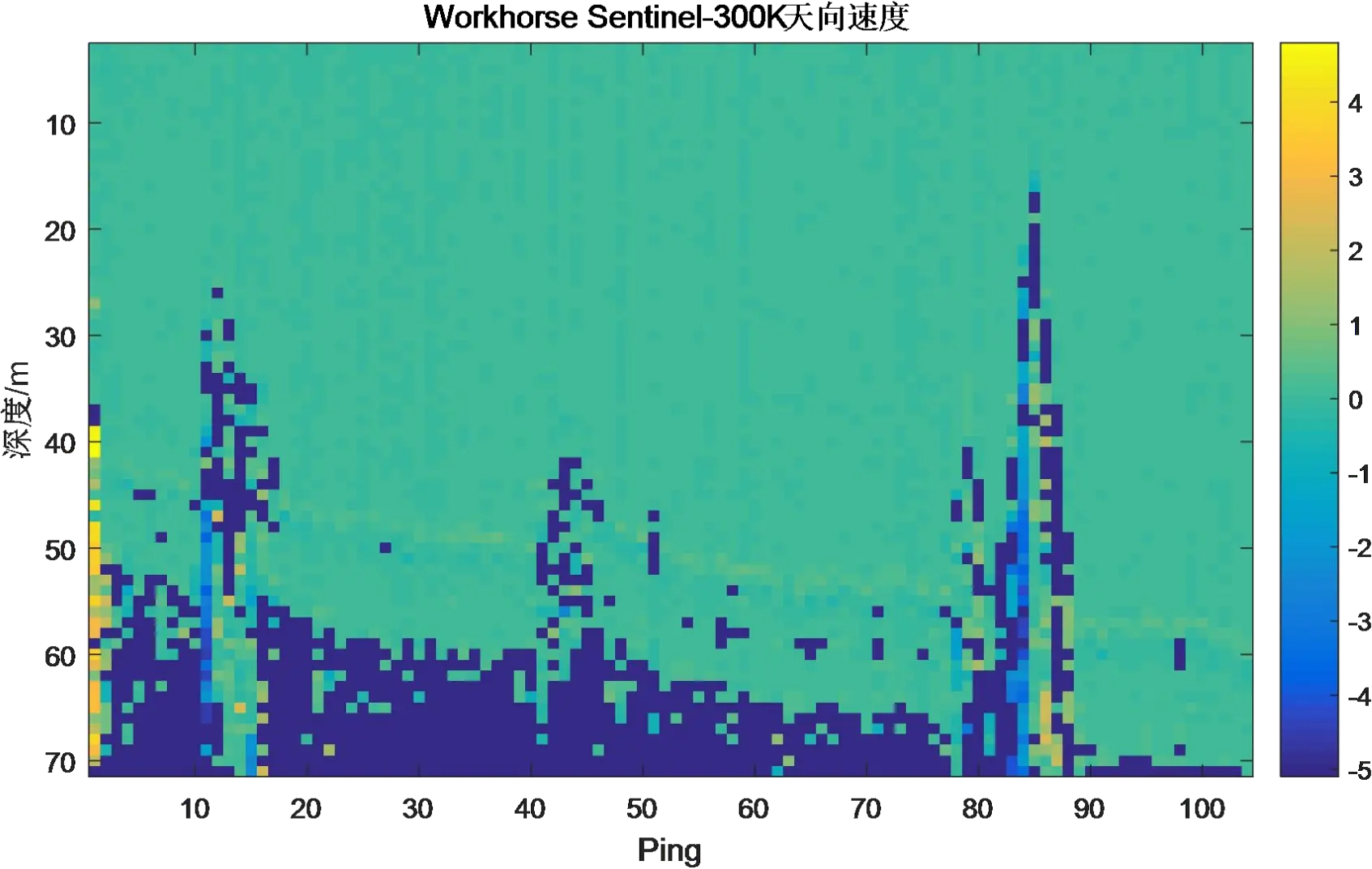
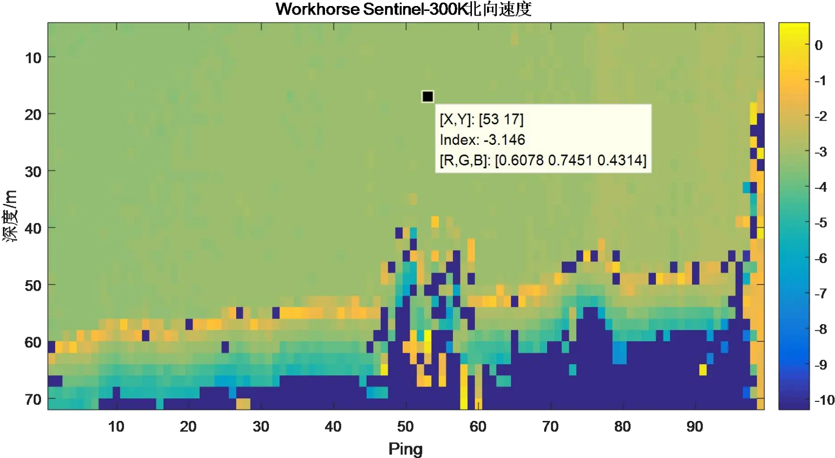
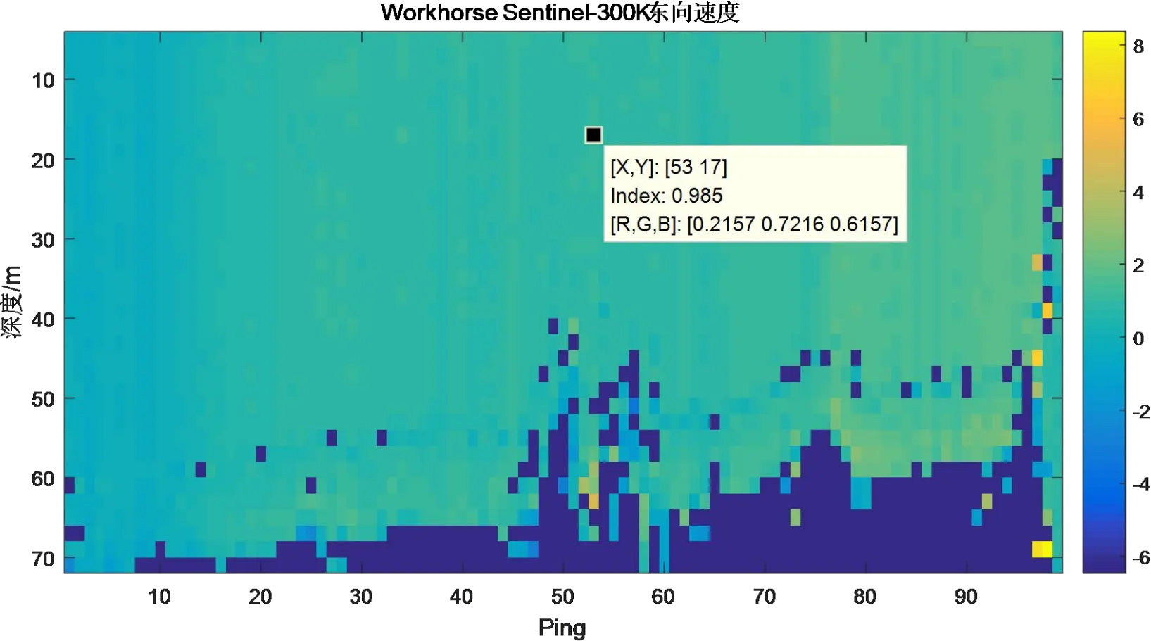
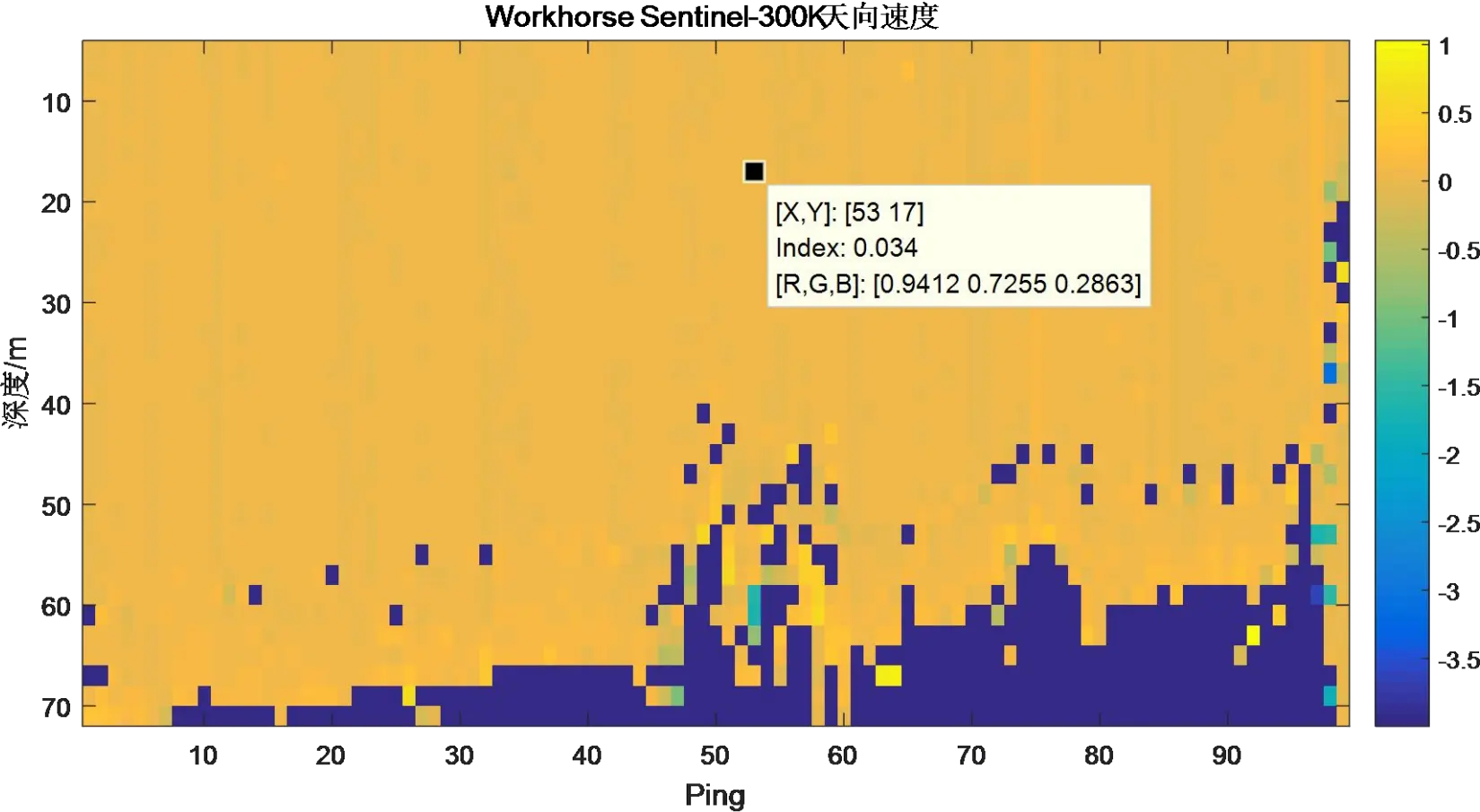
Figure 3.1.9 Static Current Measurement Results of Workhorse ADCP
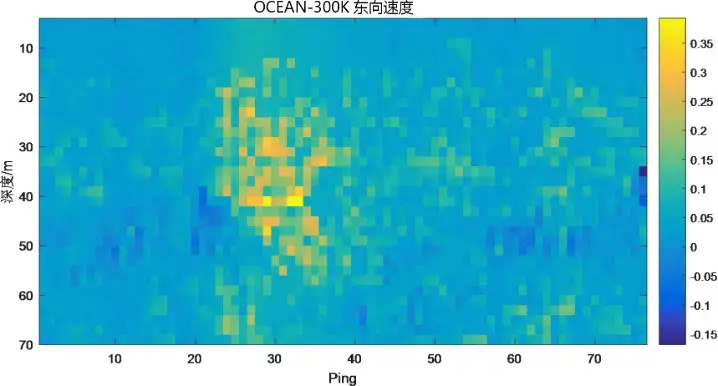
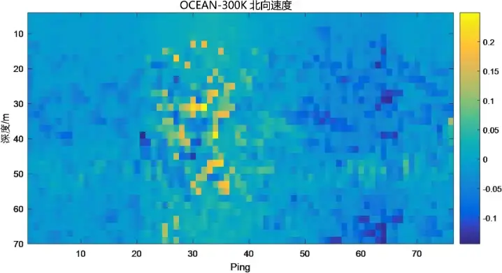
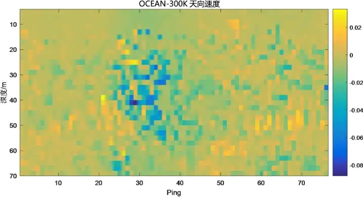
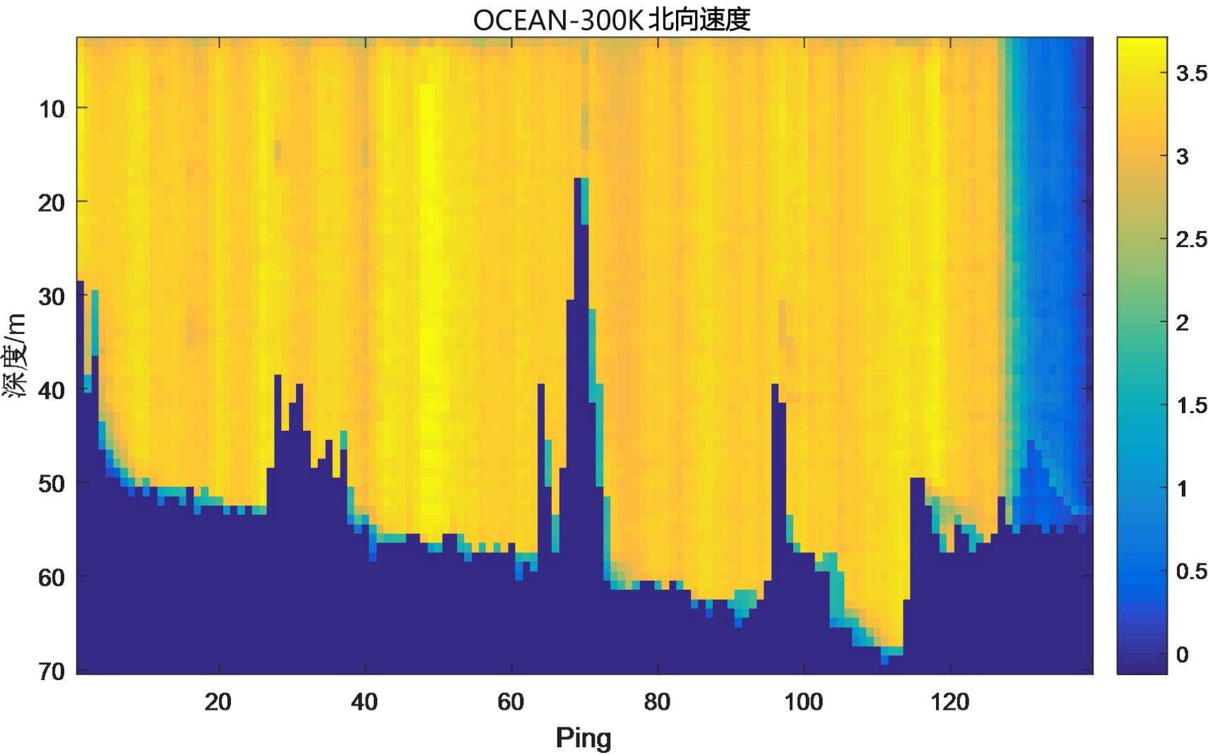
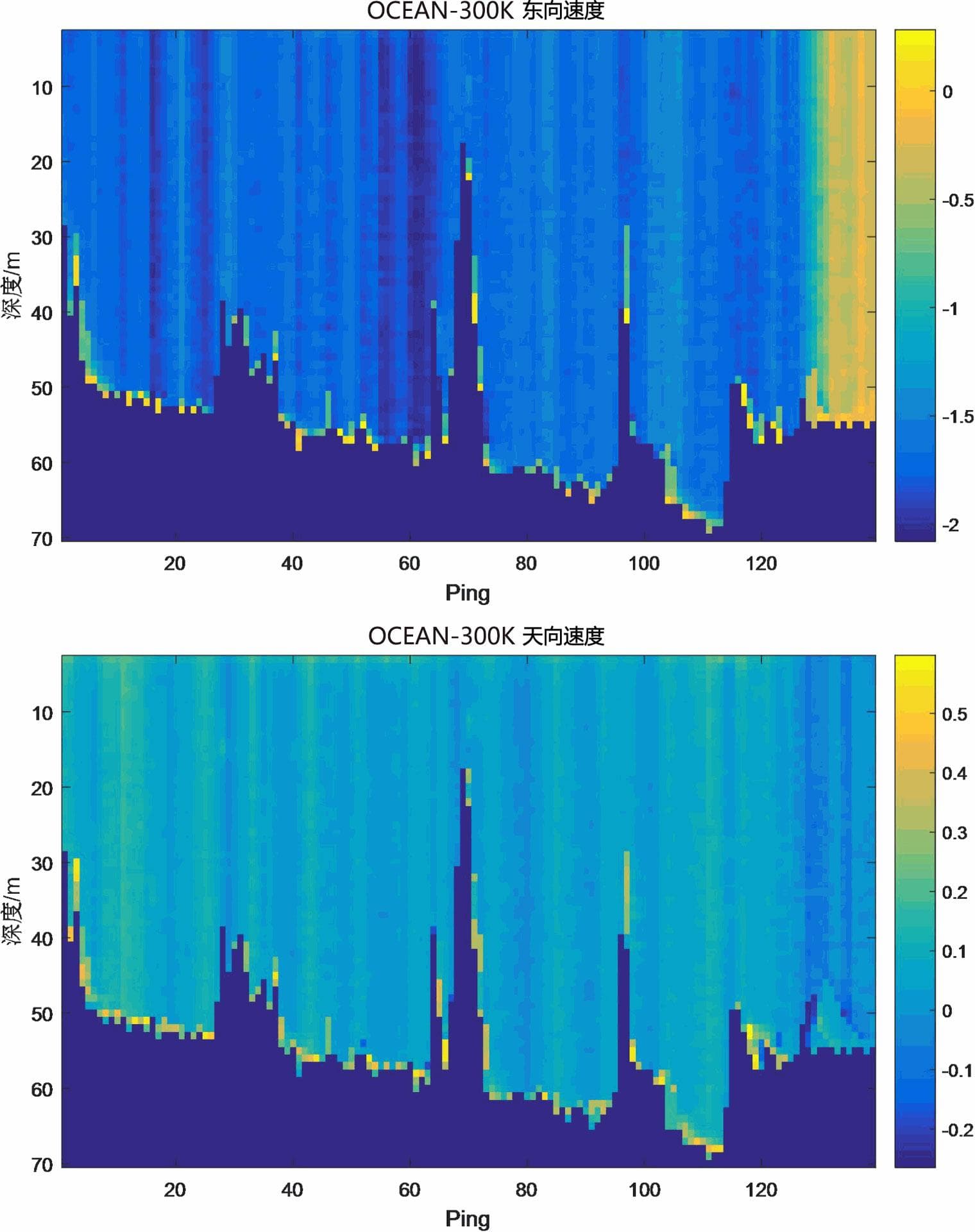
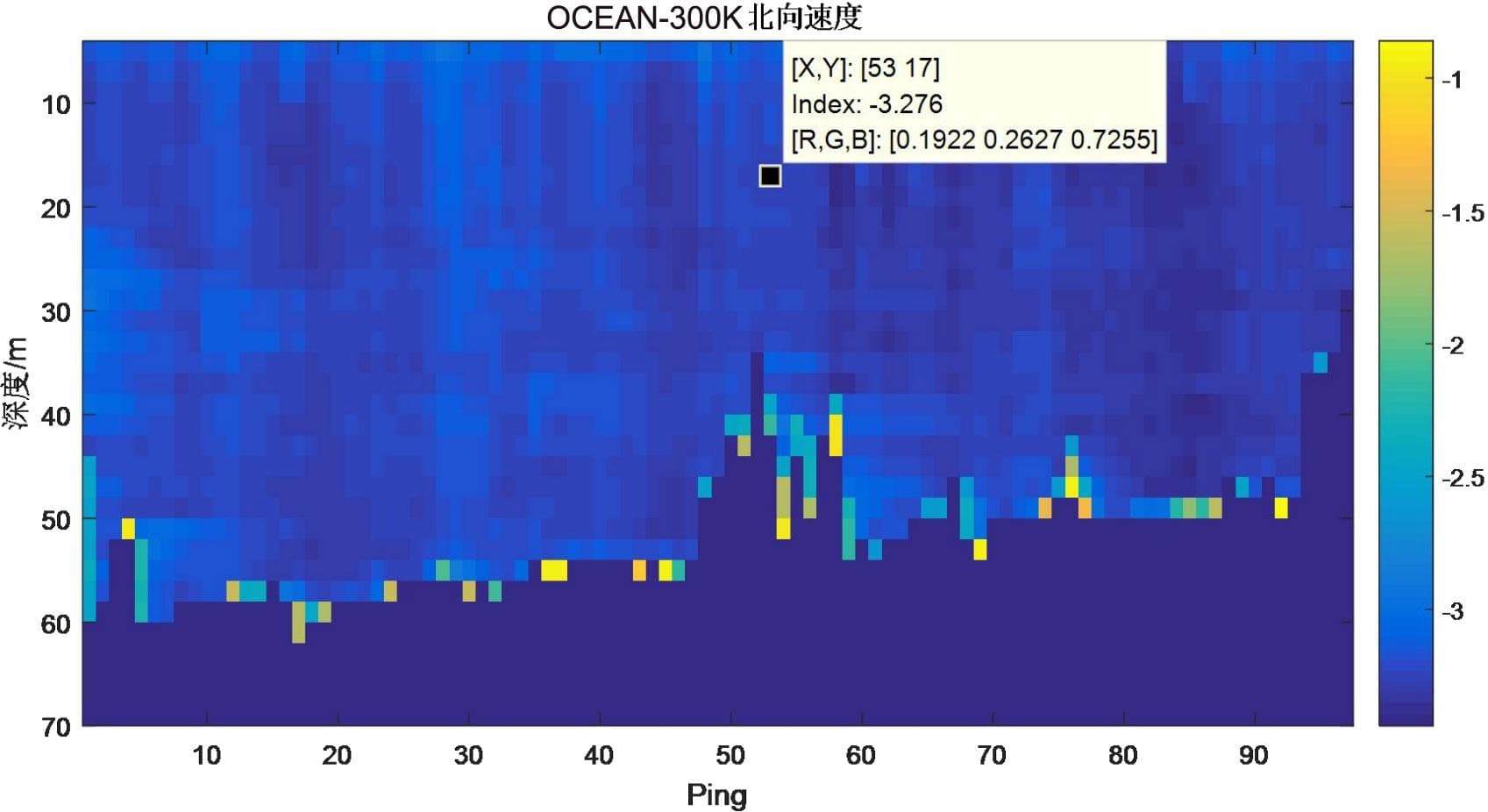
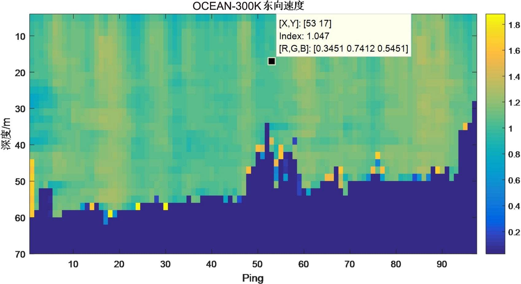
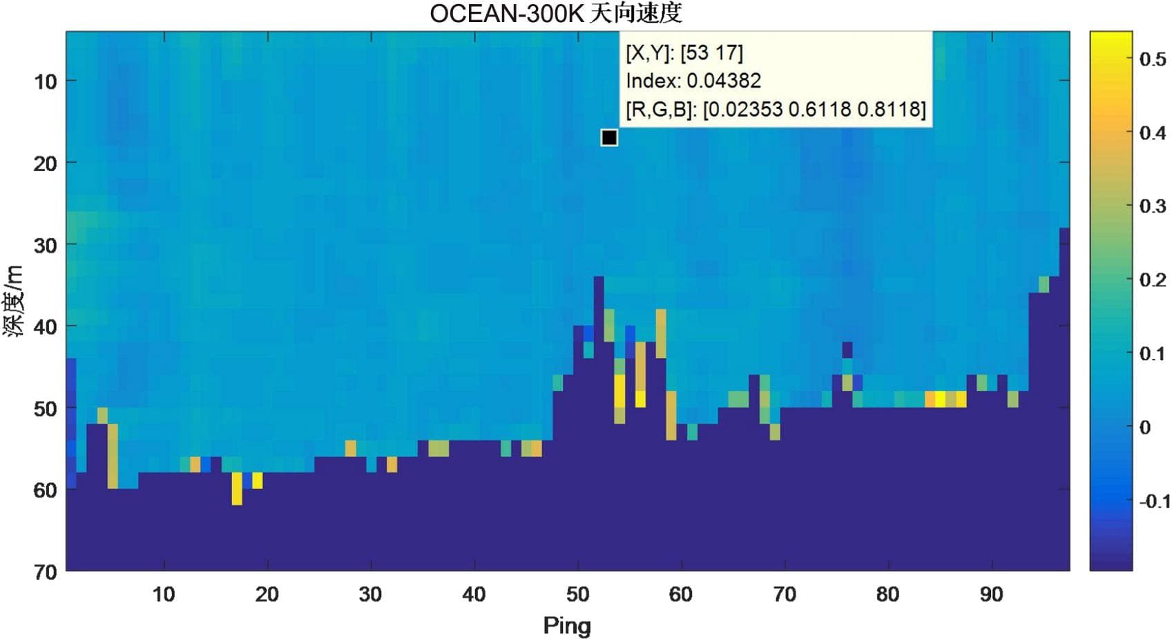
Figure 3.1.10 Static Current Measurement Results of OCEAN-300K
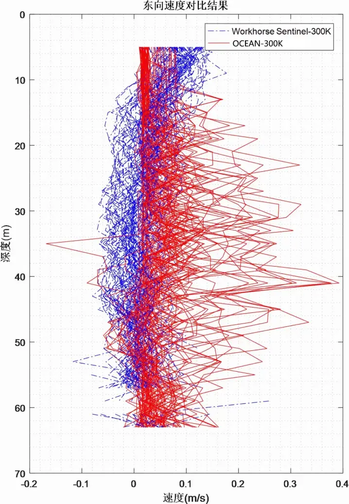
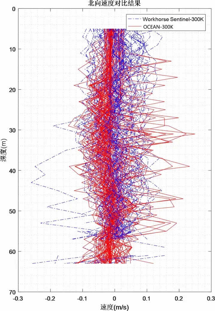
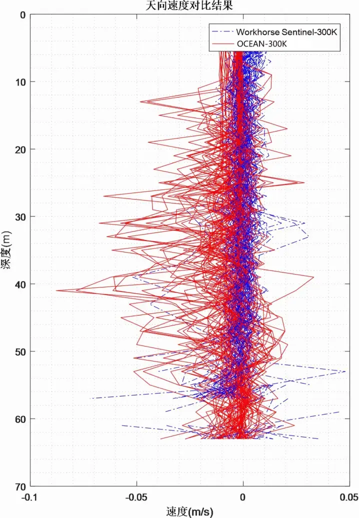
It can be seen from the time-series current measurement diagrams that the static current measurement ranges of the two devices are basically consistent.
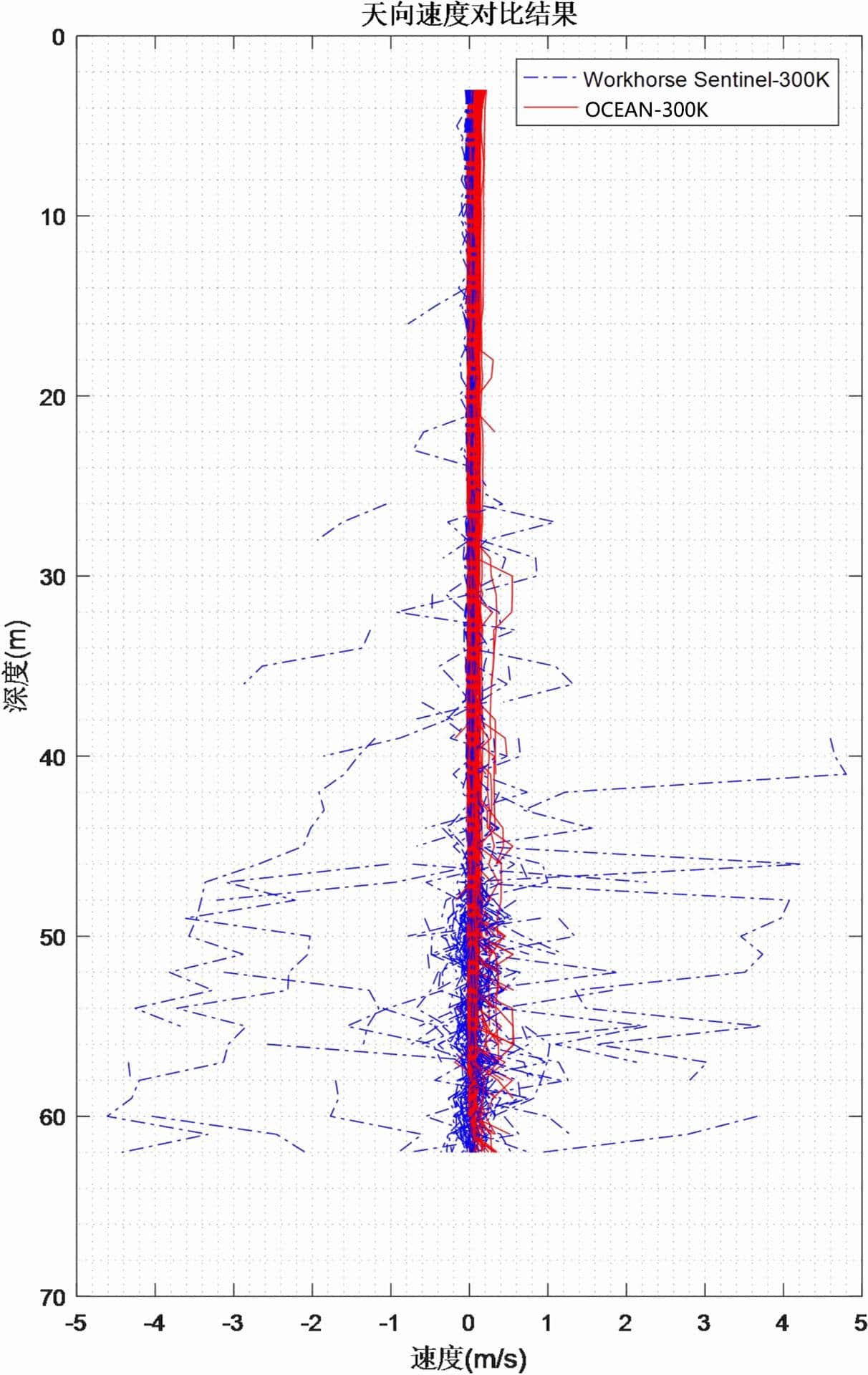
The eastward velocity ranges from -0.1 m/s to 0.3 m/s, the northward velocity ranges from -0.2 m/s to 0.3 m/s, and the vertical velocity ranges from -0.08 m/s to 0.04 m/s.
Statistical analysis was conducted on all ping measurement results of the three-direction velocities respectively, and the results are as follows:
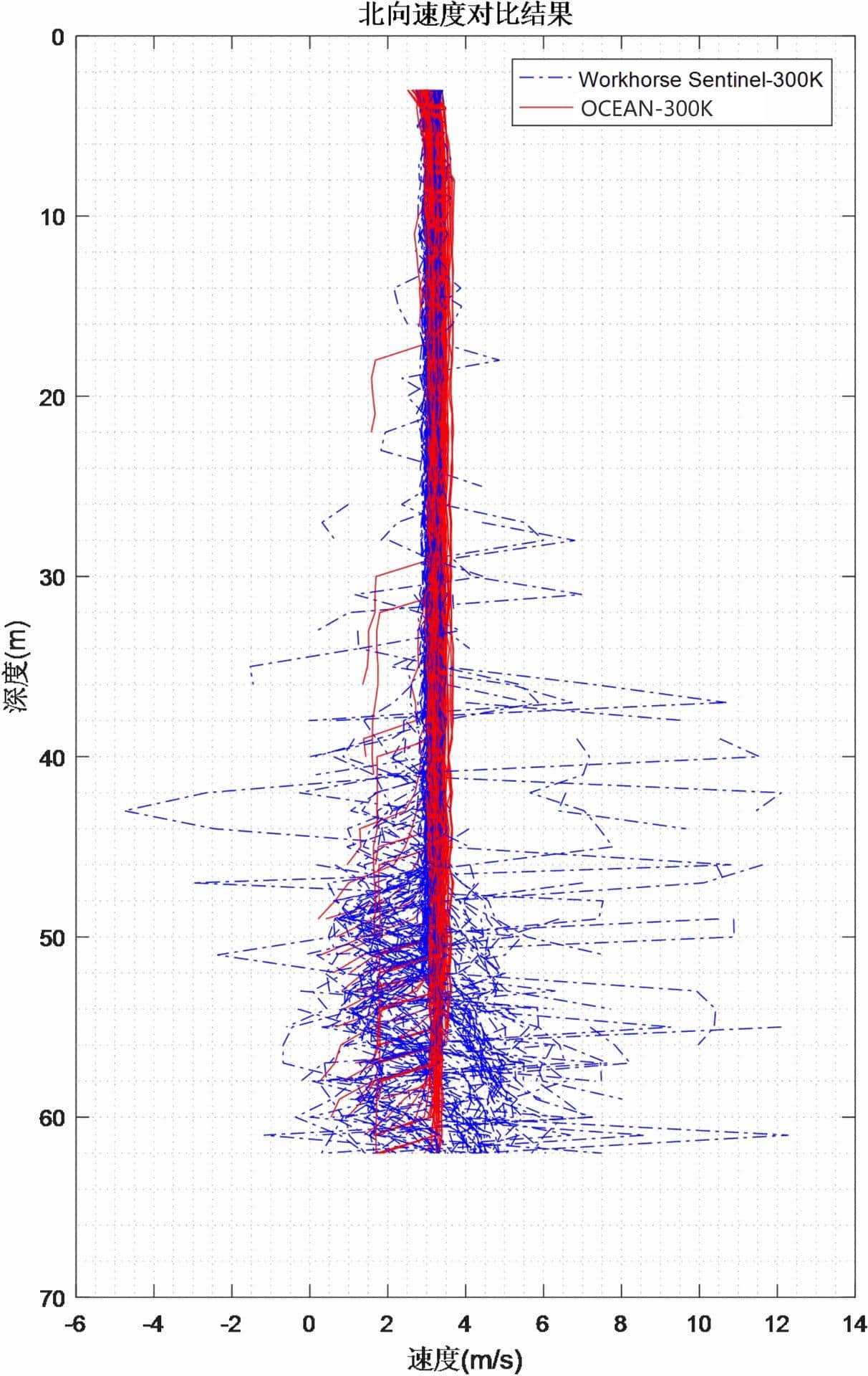
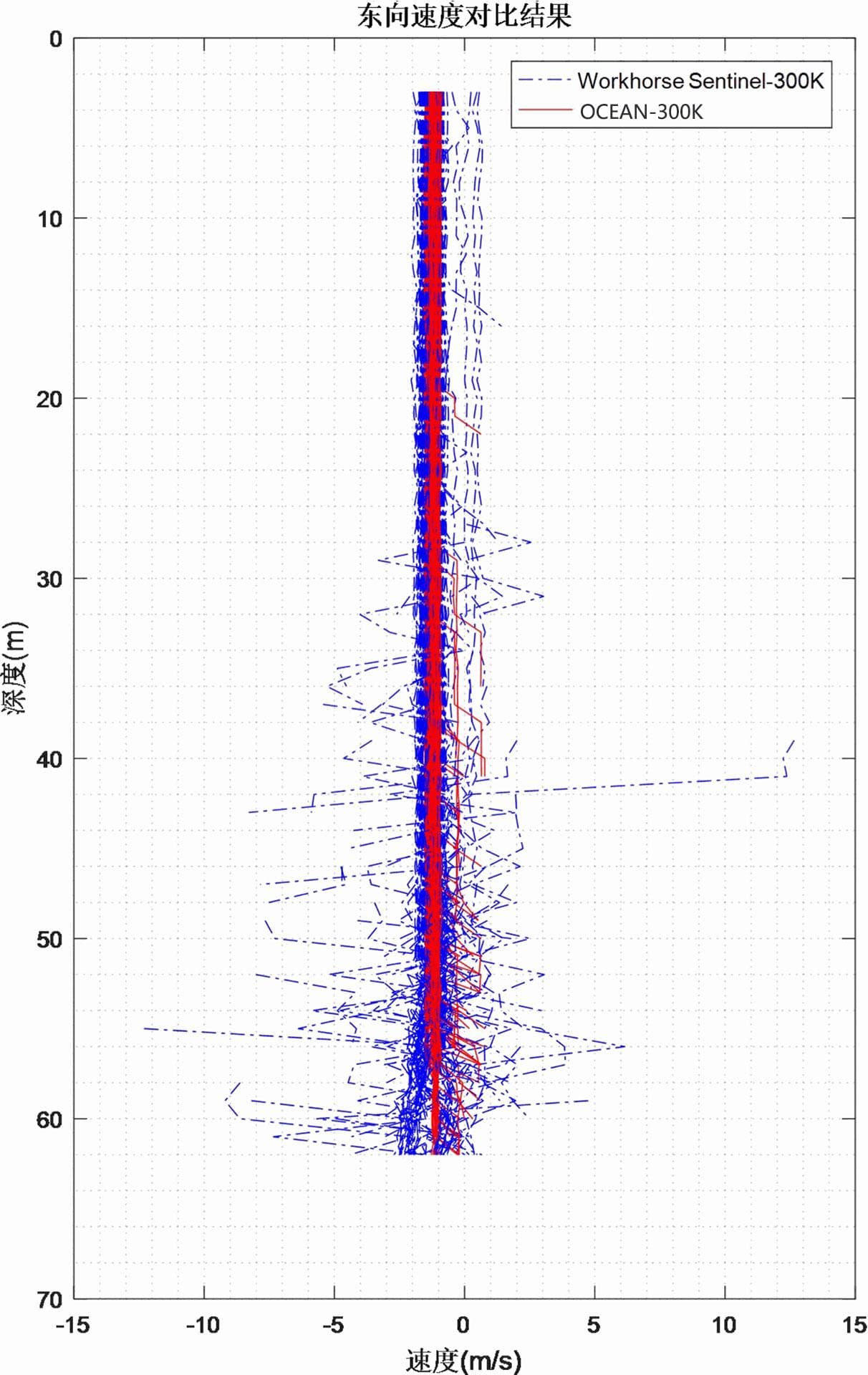
Figure 3.1.11 Multi-Ping Measurement Results of Three-Directional Velocity
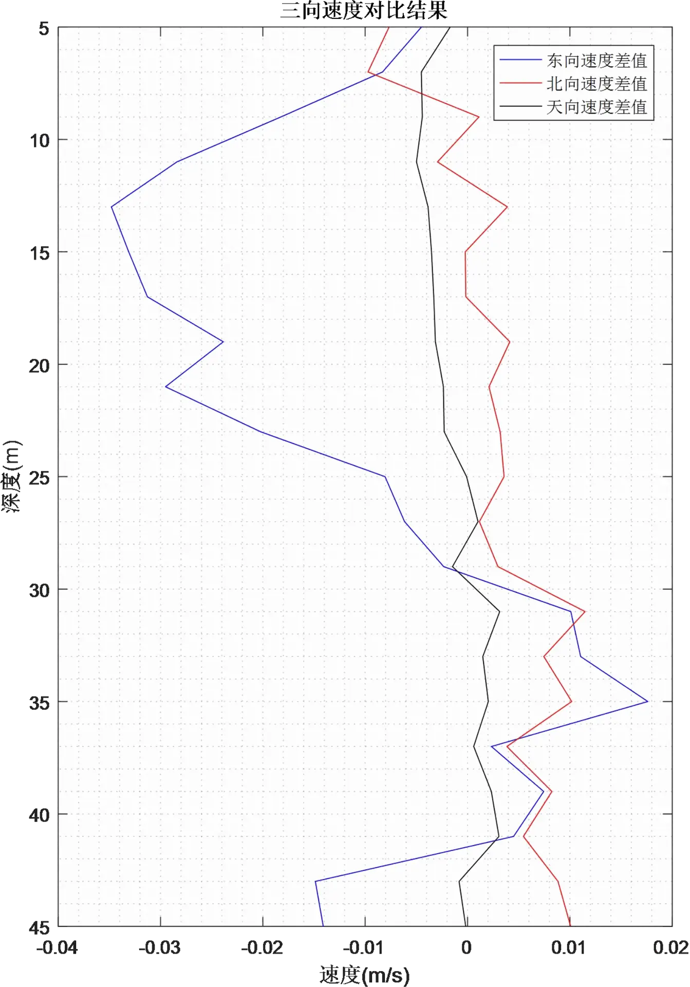
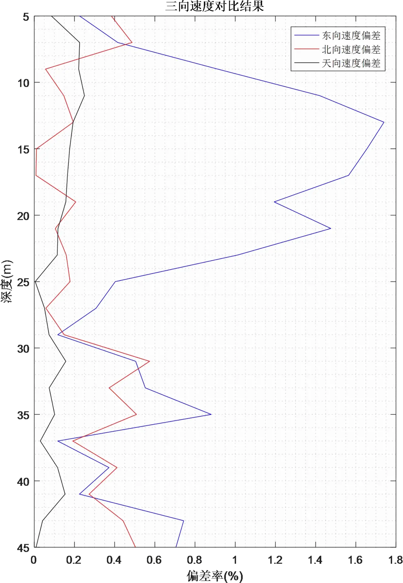
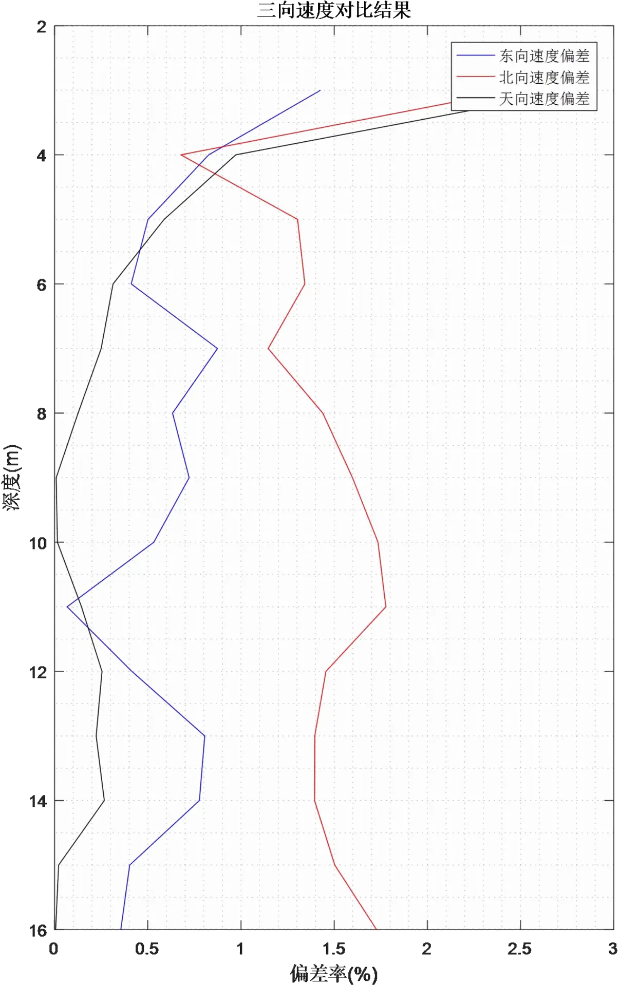
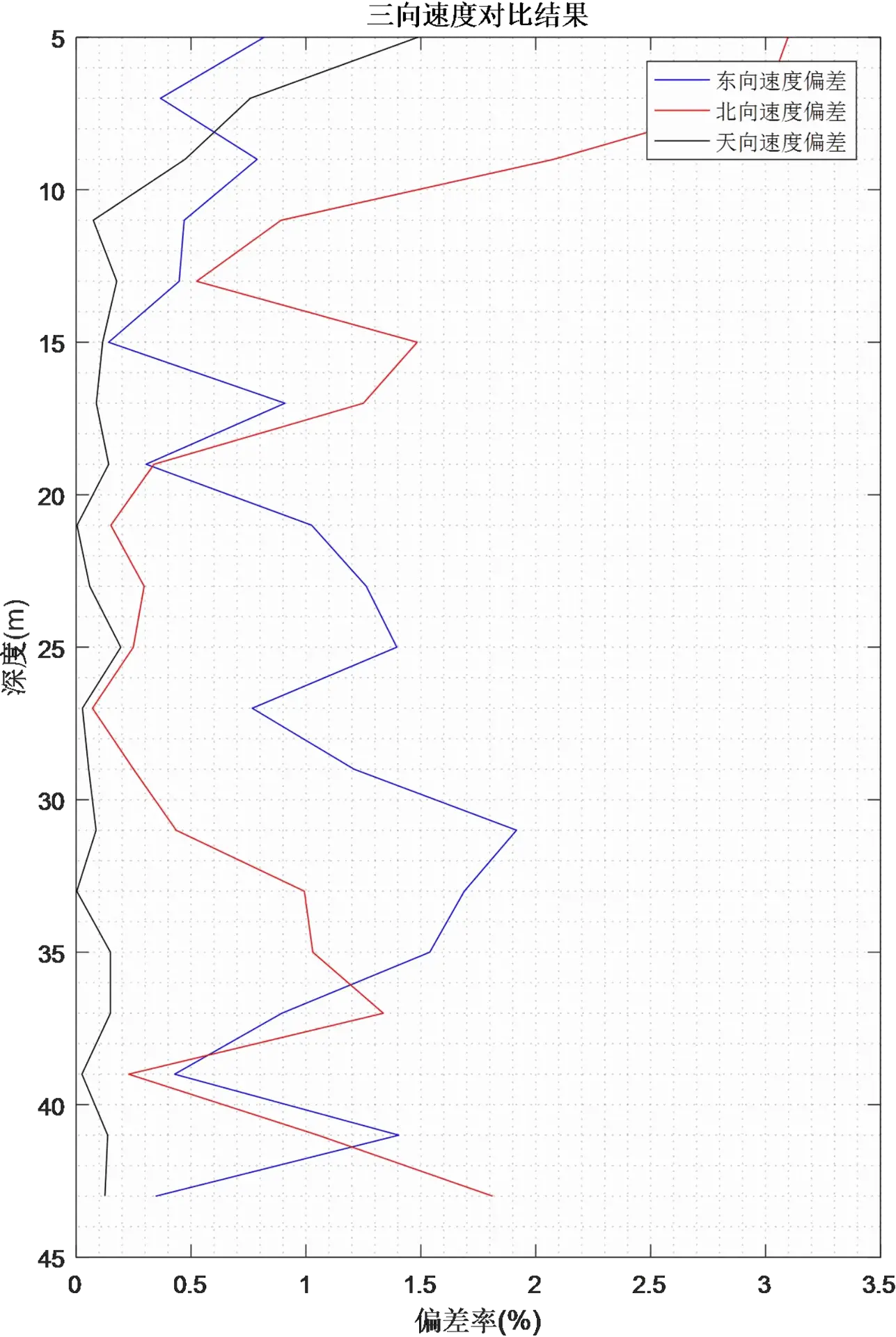
It can also be seen from the multi-Ping current measurement results that the static flow velocity measurement ranges of the two devices are basically consistent. Finally, the absolute average error and error rate of the three-direction velocities for each Ping measurement were statistically analyzed, as shown in the figure below.
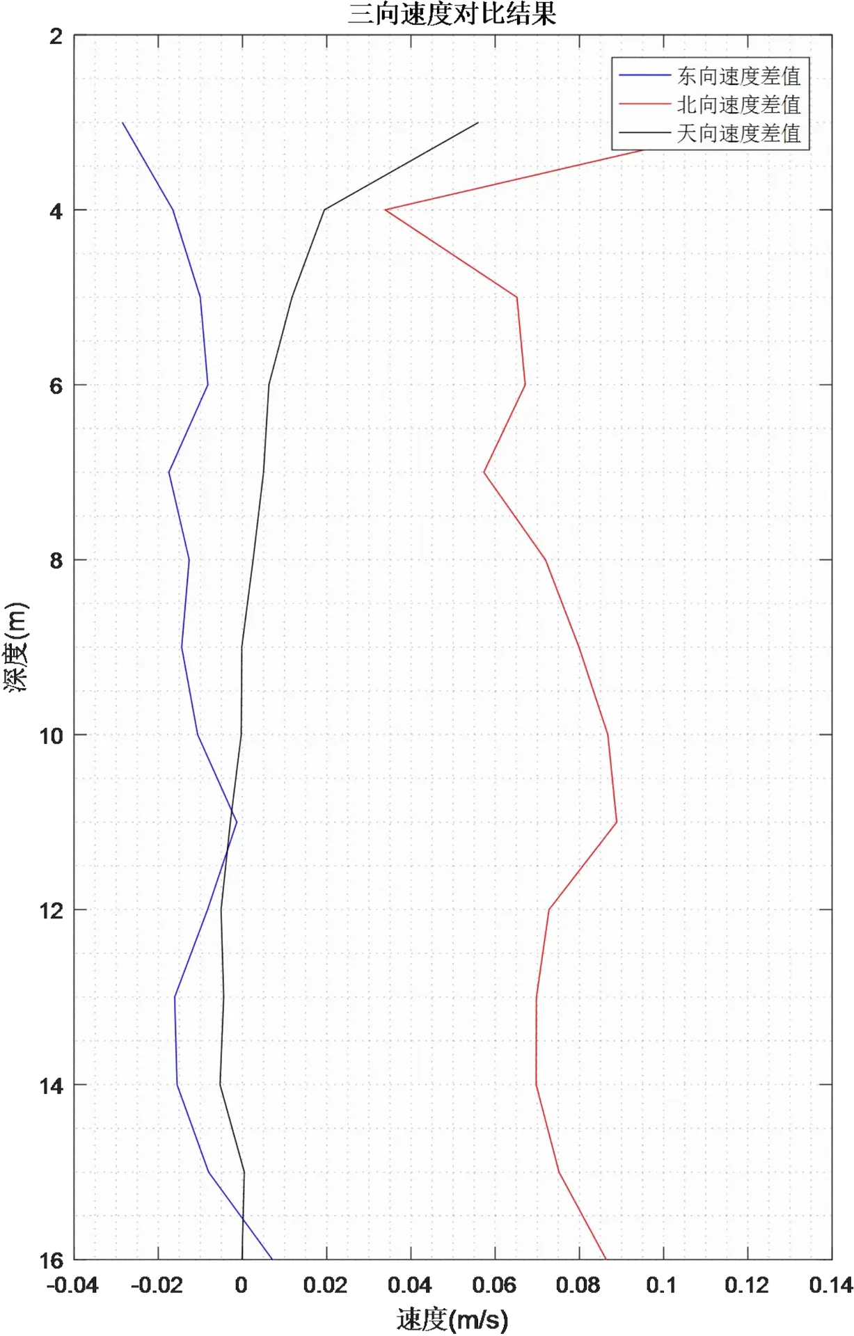
Figure 3.1.12 Relative Deviation Diagram of Three-Directional Velocity
Figure 3.1.13 Three-Directional Velocity Deviation Rate Diagram
In the bottom-mounted static current measurement mode, the relative deviation of flow velocity values measured by the two devices under the geodetic coordinate system is less than 2%. It can be concluded that in the static current measurement mode, the performance of the OCEAN ADCP is basically equivalent to that of the Workhorse ADCP, meeting the requirements for domestic substitution.
3.2 Underway Dynamic Test
3.2.1 Test Process
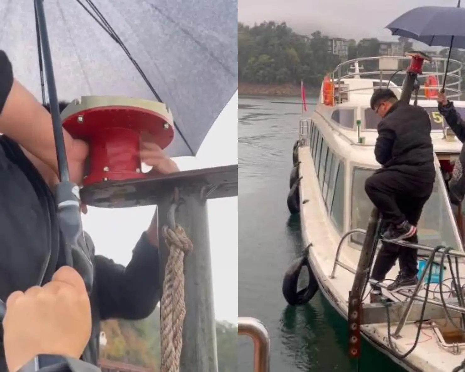
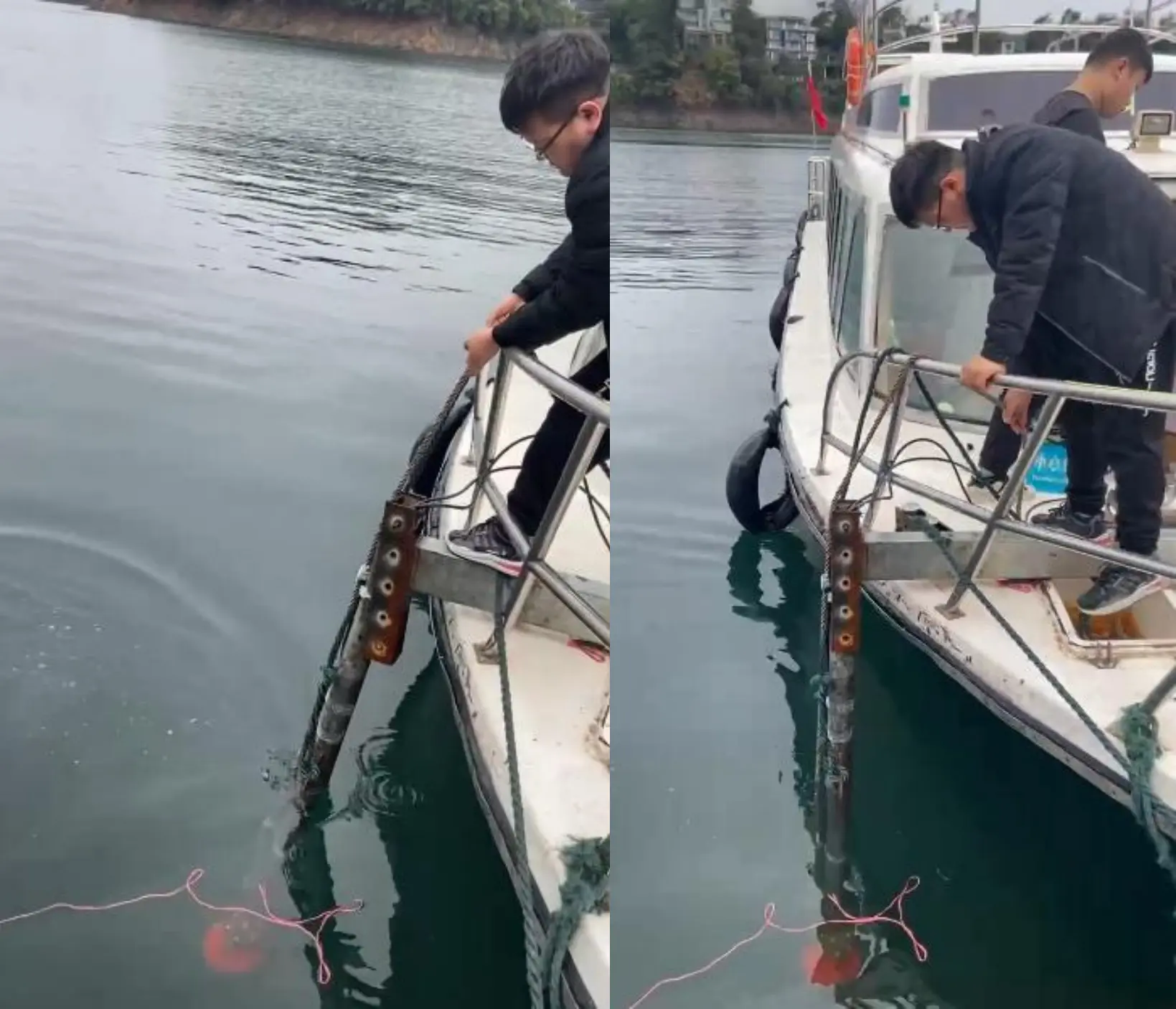
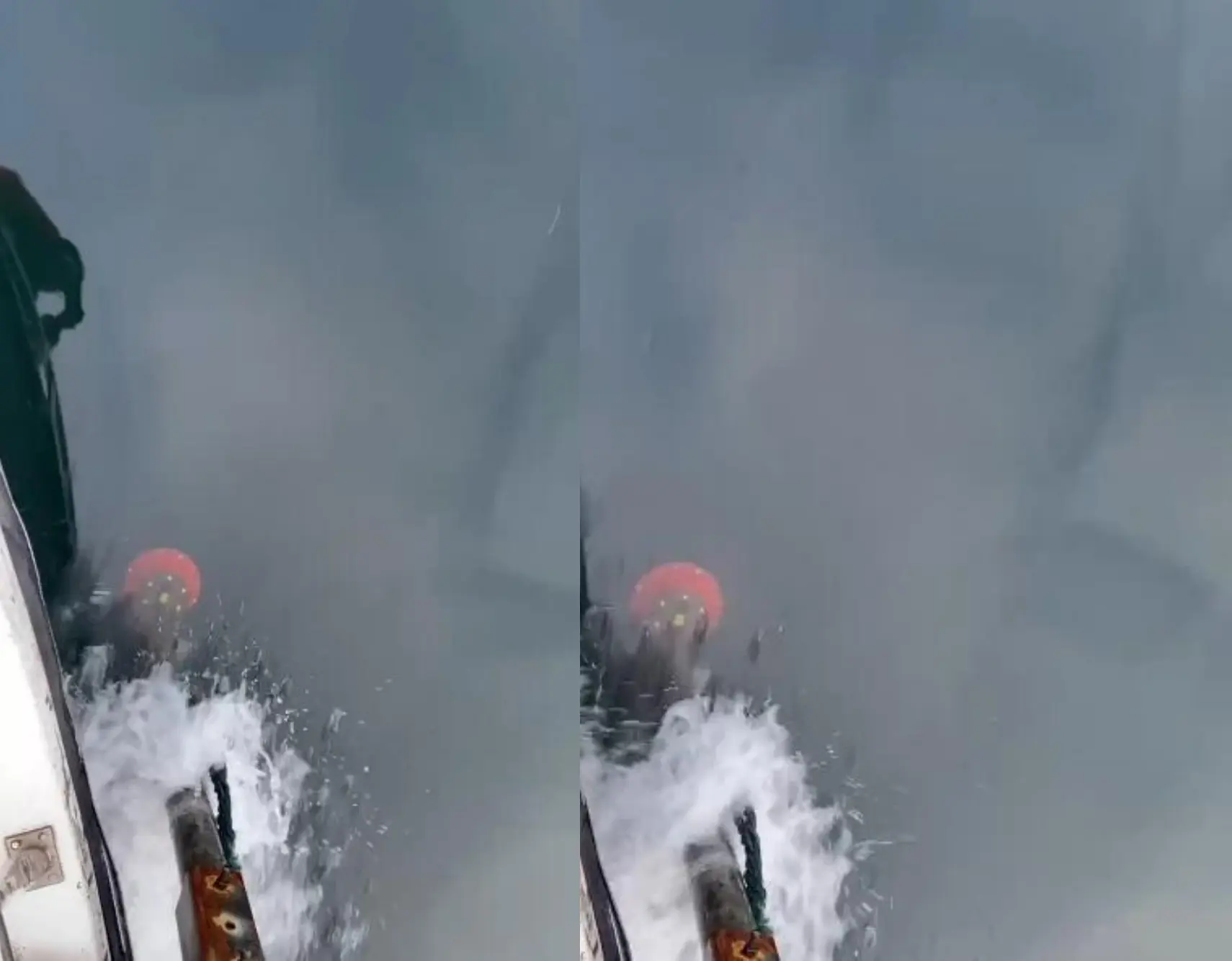
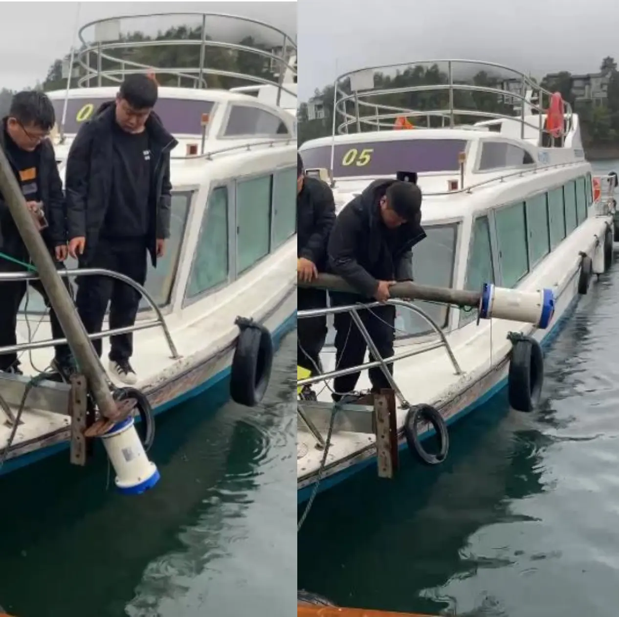
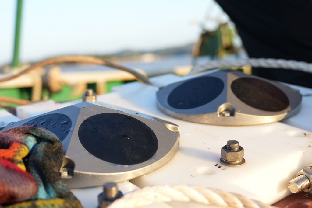
The fixation of the OCEAN-300K and Workhorse Sentinel ADCP-300K equipment started at 9:00 a.m. on March 24, 2023. The OCEAN-300K was mounted on the starboard side of the vessel, while the Workhorse Sentinel ADCP-300K was installed on the port side. The imported device was installed first. At the wharf, its cable was routed through the interior of the fixing rod to prevent cable tension and damage caused by water resistance during navigation.
Subsequently, the device was assembled onto the fixing rod. Rubber gaskets were installed between the rod and the equipment to avoid surface abrasion and damage. For secure fastening, two nuts were fitted onto each stud to prevent equipment detachment during underway operation.
After the equipment is mounted on the fixing rods, the assemblies shall be further secured to the vessel. First, move the fixing rods to the bow and align their mounting holes with those on the vessel brackets. Insert M8 long studs to fasten the rods to the hull. During bolt installation, take great care to protect the cables routed inside the fixing rods. Install bolts and nuts at all mounting holes to prevent equipment shaking during navigation, which would otherwise compromise the accuracy of measured data.
Figure 3.2.2 Installation Process of the Imported Equipment
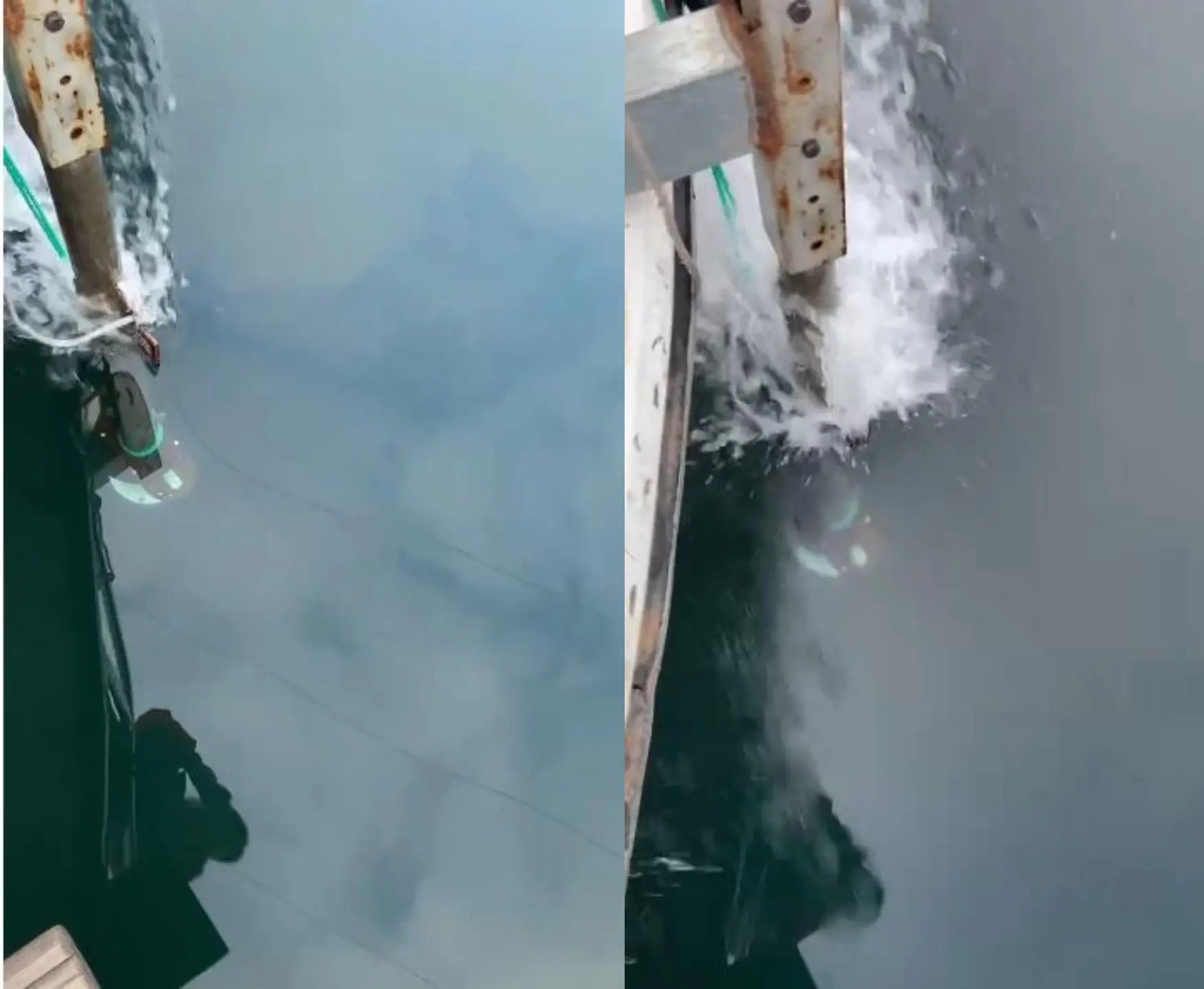
The installation of the imported equipment was completed at 10:10 a.m., after which the installation of the OCEAN-300K equipment commenced. The installation procedure followed the same steps as those for the imported equipment; the cables were routed through the fixing rod to prevent tension and damage caused by excessive water resistance. The only difference was that the fixing rod was pre-assembled with the vessel bracket in advance, and the device was then directly mounted onto the assembled bracket. Upon completion of installation, the equipment was lowered into the water.
Figure 3.2.3 Installation Process Diagram of Domestic Equipment
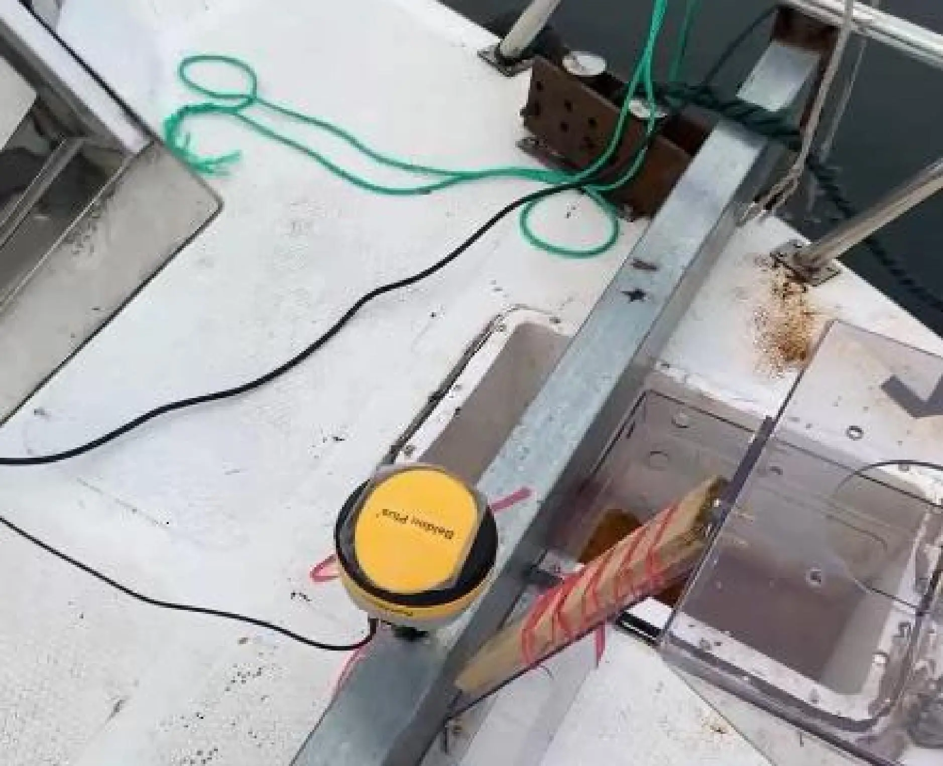
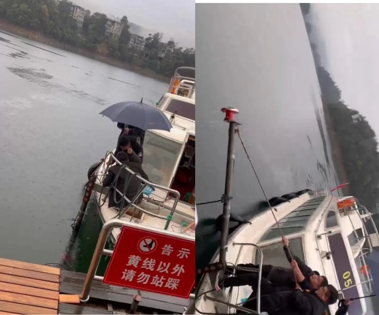
After the equipment is ready, it is necessary to install and debug the GPS. The customized fixing bracket is equipped with a dedicated screw rod for GPS. Screw the GPS onto the rod, lead the serial communication cable into the cabin, connect it to a computer, and configure the GPS output mode to GPRMC with an output frequency of 1 Hz.
Figure 3.2.5 GPS Installation Diagram
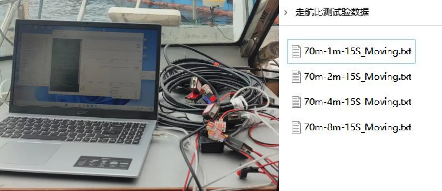
Figure 3.2.6 Software Preparation Diagram
All preparations for the domestic OCEAN-300K, imported Workhorse Sentinel ADCP-300K and GPS were completed at 11:00, and the vessel was ready to commence the underway navigation test.
A total of eight groups of underway comparison measurements were conducted in this test, including four groups for the OCEAN-300K and four groups for the Workhorse Sentinel ADCP-300K. For the first two groups of both devices, round-trip underway measurements were carried out from Southeast Lake Wharf to the 70-meter deep area of Southeast Lake (traveling from south to north). For the latter two groups, round-trip navigation tests were performed from a location approximately 500 meters away from the wharf to the waters near the Nongfu Spring water intake in Qiandao Lake.
The underway comparison test adopted an alternate transmission operating mode to ensure no mutual interference between the two devices.
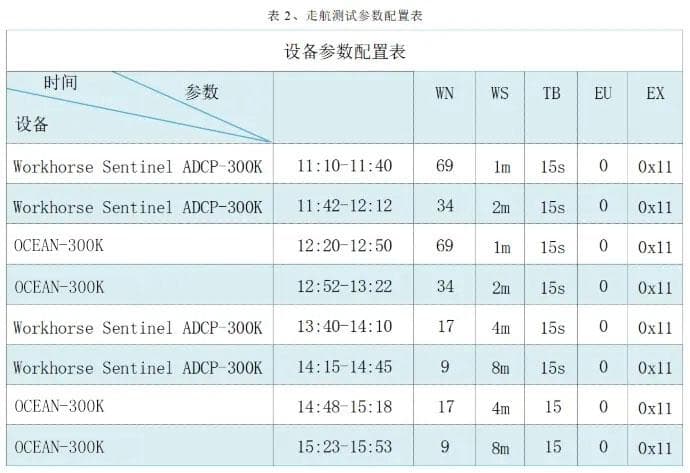
The imported device operated first. During 11:10–11:40, it sailed from the wharf to the 70-meter deep area with a resolution of 1 m. For the return voyage from 11:42 to 12:12, the resolution was set to 2 m.
The OCEAN-300K traveled from the wharf to the 70-meter deep area during 12:20–12:50 with a resolution of 1 m, and completed the return voyage from 12:52 to 13:22 at a resolution of 2 m.
From 13:40 to 14:10, the Workhorse Sentinel ADCP-300K operated at a resolution of 4 m, with the return voyage resolution set to 8 m.
Subsequently, the OCEAN-300K started operation from 14:48 to 15:18 at a resolution of 4 m, sailing from the area about 500 meters from the wharf to the waters near the Nongfu Spring water intake in Qiandao Lake, and the resolution was adjusted to 8 m for the return trip.
See the table below for detailed parameter settings.
Definition:
EU: Set the device orientation (1 – upward, 0 – downward);
TB: Set the interval between adjacent pings, namely the working cycle;
WN: Set the number of measurement layers;
WS: Set the layer thickness;
EX: Set the coordinate system;
The underway test was completed at 16:30 upon arrival at the wharf, and the equipment disassembly work was started subsequently.
Figure 3.2.10 Dismantling Diagram of Workhorse Sentinel ADCP-300K Equipment
Figure 3.2.11 Dismantling Diagram of OCEAN-300K Equipment
3.2.2 Test Results
The test results at resolutions of 1 m and 2 m are compared in detail below. Similarly, Matlab was used to unpack and comparatively analyze the PD0 data recorded by the two devices.
(1) Comparison of Current Measurement Results at 1 m Layer Thickness
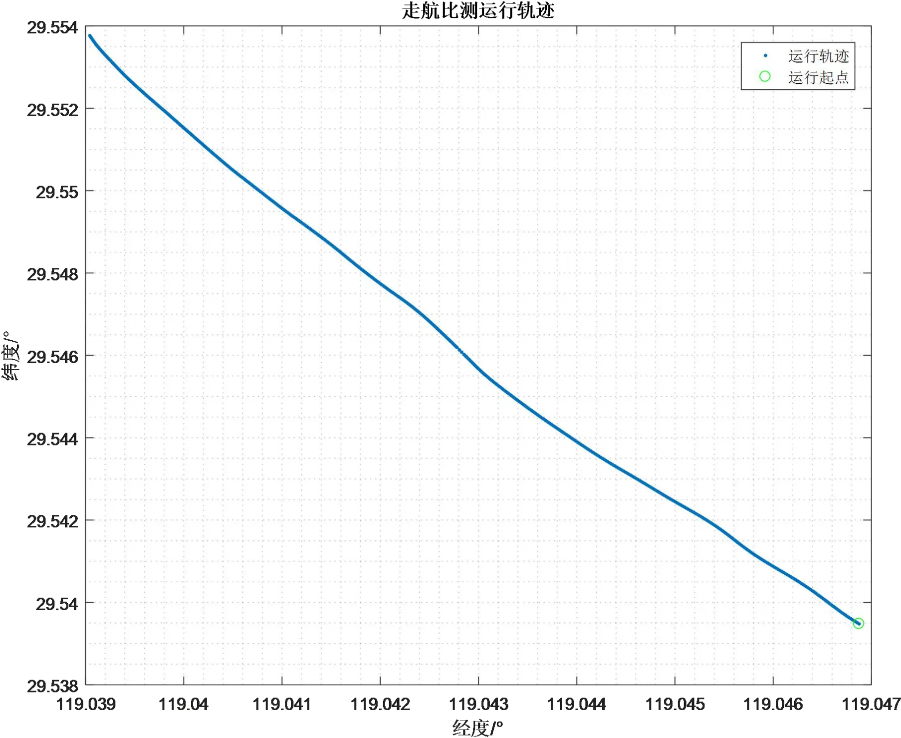
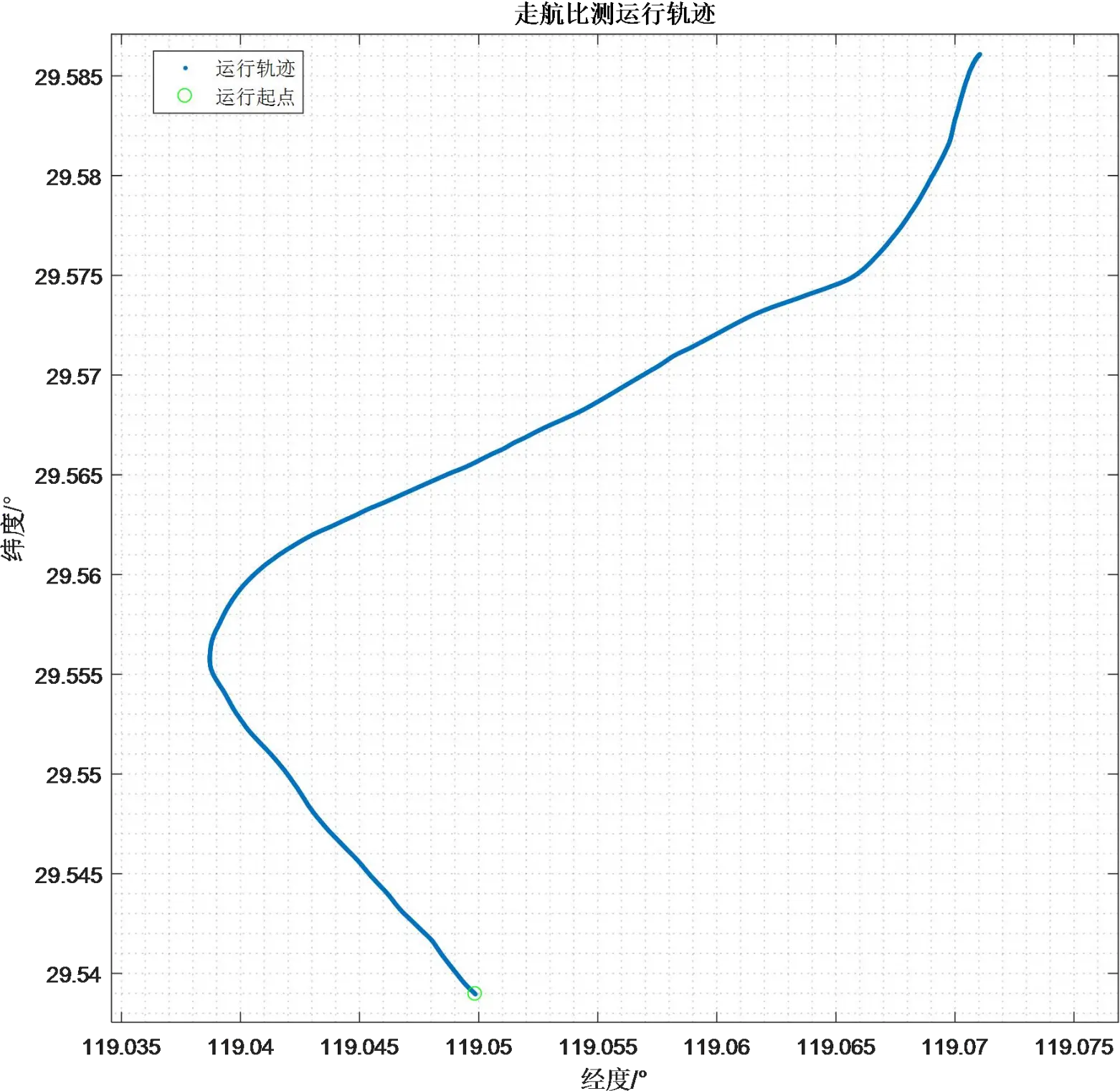
Figure 3.2.12 Underway Current Measurement Trajectory — Layer Thickness of 2 m
According to the trajectory recorded by GPS, the overall moving direction during the 1 m resolution comparison test was from southeast to northwest.
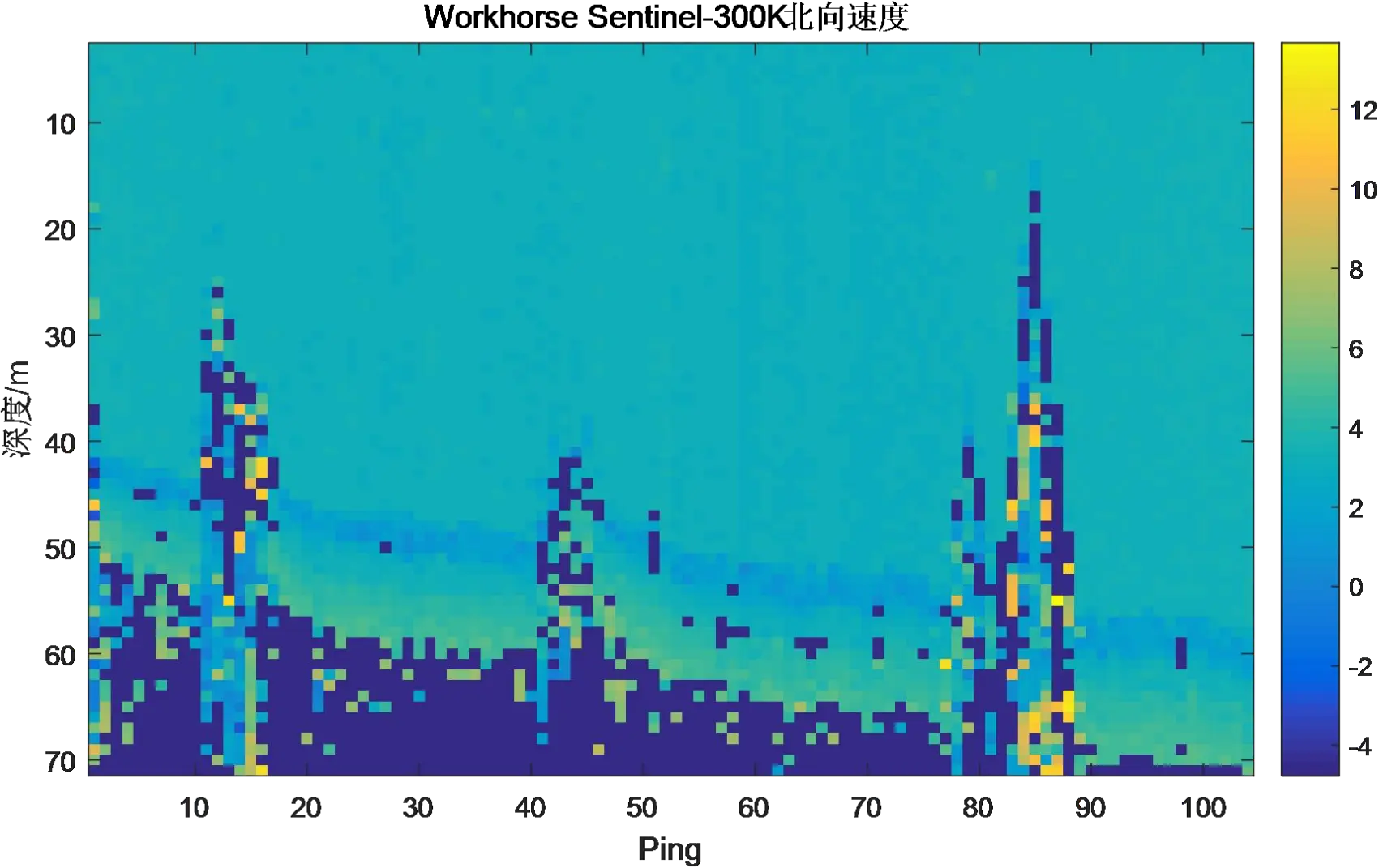
Figure 3.2.13 Underway Current Measurement Results of Workhorse — Layer Thickness 1 m
Figure 3.2.14 Underway Current Measurement Results of OCEAN-300K – 1 m Layer Thickness
Figure 3.2.15 Three-Dimensional Velocity Multi-Ping Current Measurement Results — 1 m Layer Thickness
Figure 3.2.17 Comparison Diagram of Three-Directional Velocity Deviation Rate
It can be seen from the current measurement comparison results that the dynamic current measurement ranges of the two devices are basically consistent. The eastward velocity ranges from -2.5 m/s to 0.5 m/s, the northward velocity ranges from 2.5 m/s to 4.0 m/s, and the vertical velocity ranges from -0.05 m/s to 0.1 m/s. In addition, the current measurement data of the OCEAN ADCP presents higher stability than that of the Workhorse.
Under the underway measurement mode with a layer thickness of 1 m, the relative deviation of current velocity values measured by the two devices in the geodetic coordinate system is less than 2%.
(2) Comparison of Current Measurement Results at 2 m Layer Thickness
Figure 3.2.18 Underway Current Measurement Trajectory – 2 m Layer Thickness
Judging from the trajectory recorded by GPS, the overall movement direction of the 2m-resolution comparison test is from south to north.
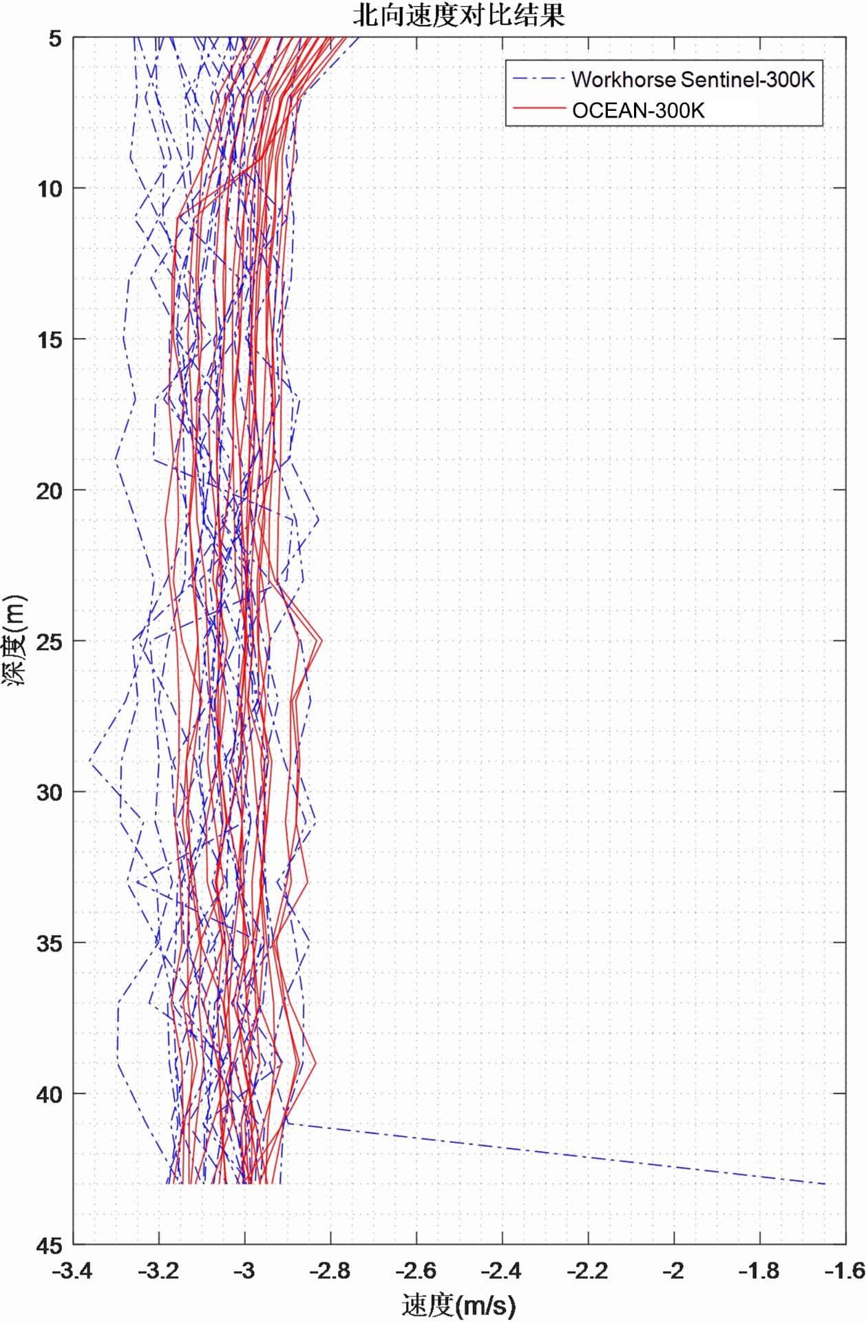
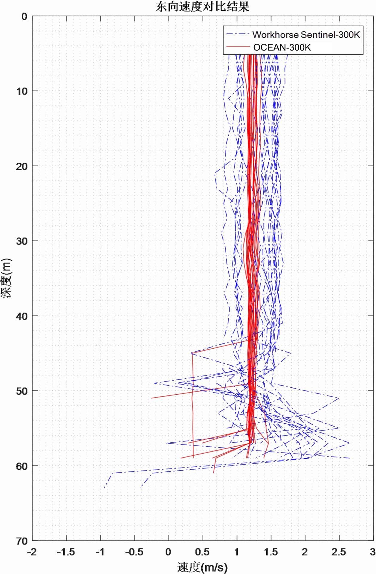
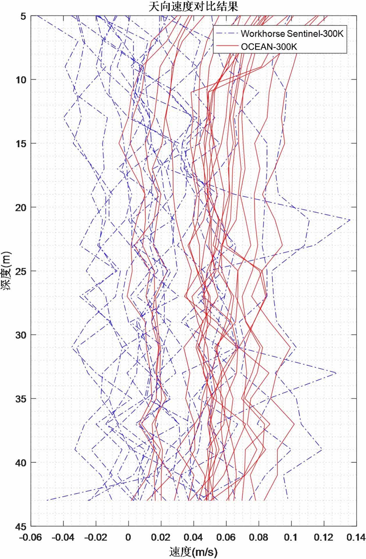
Figure 3.2.19 Underway Current Measurement Results of Workhorse – 2 m Layer Thickness
Figure 3.2.20 Underway Current Measurement Results of OCEAN-300K – 2 m Layer Thickness
Figure 3.2.21 Multi-Ping Current Measurement Results of Three-Directional Velocity – 2 m Layer Thickness
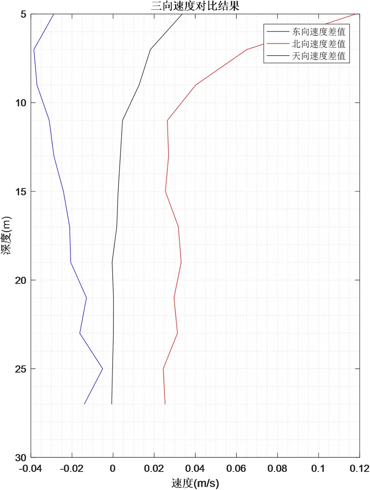
Figure 3.2.22 Comparison of Relative Deviation of Three-Directional Velocity
Figure 3.2.23 Comparison Diagram of Three‑Directional Velocity Deviation Rate
It can be concluded from the current measurement comparison results that the dynamic current measurement ranges of the two devices are basically consistent.
The eastward velocity ranges from 0.5 m/s to 2.0 m/s, the northward velocity ranges from -3.4 m/s to -2.8 m/s, and the vertical velocity ranges from -0.06 m/s to 0.1 m/s.
In the underway measurement mode with a layer thickness of 2 m, the relative deviation of current velocity measured by the two devices under the geodetic coordinate system is less than 2%.
Based on the comprehensive analysis and comparison of underway current measurement data, it is verified that the performance of the OCEAN ADCP is basically equivalent to that of the Workhorse unit in underway mode, meeting the requirements for domestic substitution.
IV. Test Conclusions
In this comparative test, two types of equipment were adopted: the self‑developed and self‑manufactured OCEAN‑300K and the Workhorse Sentinel ADCP‑300K produced by TRDI (USA). A comprehensive comparison of current measurement performance was conducted respectively in the bottom‑mounted static mode and underway navigation mode.
To accurately compare the measurement performance of the two devices, MATLAB was used to parse and compare the PD0 raw data recorded by both instruments.
The comparison results show that the relative deviation of measured current velocity between the two products is less than 2% in both static and underway modes.
It is confirmed that their current measurement performance is equivalent. The self‑developed OCEAN ADCP can fully replace the high‑precision ADCP products of TRDI. The velocity profile data measured by the OCEAN ADCP in subsequent applications is authentic and reliable.
位置图1.webp)
位置图2.webp)
位置图.webp)