The moment an autonomous underwater vehicle (AUV) submerges, it loses the positioning signal that every other autonomous system on Earth takes for granted. A self-driving car has GPS plus lane markings plus landmark recognition. A delivery drone has GPS plus vision. An AUV has none of these — and yet it must fly precise survey lines for hours, sometimes days, often in complete darkness, over terrain no one has ever mapped.
How? The answer is a carefully engineered navigation stack built around two sensors: a Doppler Velocity Log (DVL) that measures the vehicle’s velocity over the seafloor, and an Inertial Navigation System (INS) that tracks its motion between every other measurement. This article explains how they work together across a complete AUV mission — and where the navigation actually succeeds or fails.
This is not a technology overview. For that, see our guides on how underwater GPS works and how a DVL measures velocity. This article takes the mission-engineering view: what happens at each phase of a real AUV mission, how position error accumulates, and how to architect a navigation system that stays inside your accuracy budget.
Summary
AUV navigation is error-budget management, not sensor shopping. The question is never “which sensors should I buy” — it’s “how much position error can my mission tolerate, and which sensor combination keeps me inside that budget?”
Three numbers define the performance envelope: a well-integrated DVL + INS system holds drift to 0.05–0.1% of distance traveled (5–10 m over a 10 km mission). A low-cost configuration (DVL + basic IMU + compass) demonstrated 1.5% of distance traveled in sea trials. An AUV with no DVL at all, relying on periodic surfacing for GPS fixes every 30 minutes, accumulated an average error of 82 meters over a 32 km simulated path. The difference between these numbers is the difference between a survey that meets specification and one that must be re-flown.
Table of Contents
- The GPS-Denied Problem, Quantified
- The AUV Navigation Stack: Standard Architecture
- The Mission Lifecycle: Six Phases Where Navigation Lives or Dies
- The Error Budget: Where Accuracy Actually Goes
- Three Mission Profiles, Three Architectures
- Failure Modes: What Breaks AUV Navigation
- Practical Integration Checklist
- Frequently Asked Questions
1. The GPS-Denied Problem, Quantified
GPS radio waves at 1.5 GHz are absorbed by seawater within centimeters — the physics of this is covered in detail in our underwater GPS guide. For AUV engineering, the consequence is absolute: from the moment of submergence to the moment of surfacing, the vehicle has no external absolute position reference — unless a surface vessel is actively tracking it with acoustic positioning.
What does that cost, in concrete numbers? It depends entirely on what the AUV carries:
| Navigation Configuration | Typical Position Error | Source |
|---|---|---|
| Unaided INS (tactical-grade MEMS) | Kilometers per hour — grows quadratically | Published INS drift specifications |
| INS + DVL + compass + pressure (low-cost IMU) | ~1.5% of distance traveled (CEP) | “Haiwei 1” AUV sea trials |
| INS + DVL (navigation-grade, well integrated) | 0.05–0.1% of distance traveled | Industry-standard performance figure |
| No DVL — surfacing for GPS every 30 min | Average 82 m, max 262 m over a 32 km path | Simulation study of surfacing-based navigation |
Read that table carefully — the spread is enormous. An unaided INS is useless within an hour. A low-cost DVL-aided stack is usable for coastal work. A navigation-grade DVL + INS stack holds drift tight enough for high-resolution surveys over full mission lengths. And the “just surface for GPS” fallback costs you an average of 82 meters of error over 32 kilometers — acceptable for reconnaissance, unacceptable for any survey that requires consistent line spacing.
2. The AUV Navigation Stack: Standard Architecture
Modern AUVs converge on a remarkably standard navigation stack. The differences between a $200,000 survey AUV and a $2 million survey AUV are mostly in the grades of these components, not in the architecture itself.
| Sensor | What It Measures | Update Rate | Role in Navigation |
|---|---|---|---|
| GPS/GNSS receiver | Absolute position — surface only | 1–10 Hz | Initialization and drift reset at start/end of mission |
| INS (accelerometers + gyros) | Linear acceleration, angular rate | 100–400 Hz | Continuous dead reckoning — the backbone |
| DVL | 3D velocity over seafloor, altitude | 2 Hz | Bounds INS drift — the critical aiding sensor |
| Pressure sensor | Depth | 10–100 Hz | Z-axis reference — cheap and reliable |
| AHRS / compass | Roll, pitch, heading | 10–100 Hz | Attitude reference for coordinate transforms |
| USBL transponder (optional) | Acoustic position from surface vessel | 0.5–2 Hz | Periodic absolute fixes during supported missions |
The data flow: all sensors feed a Kalman filter running on the vehicle’s navigation computer. The INS provides the high-rate prediction — “based on acceleration and rotation since the last update, I predict the vehicle is here.” Every external measurement — a DVL velocity reading at 2 Hz, a USBL position fix, a pressure-derived depth — updates and corrects that prediction. The filter’s output is a continuous position, velocity, and attitude estimate at INS rate.
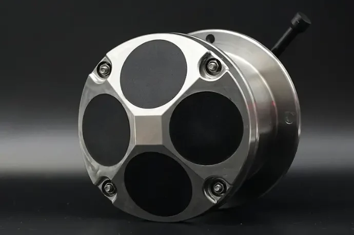
The DVL’s role deserves emphasis, because it’s architecturally unique. The INS, AHRS, and pressure sensor all measure the vehicle from inside. GPS and USBL provide external references but are unavailable most of the mission. The DVL is the only sensor that provides continuous, self-contained, ground-referenced measurement during the entire underwater portion of the mission. How it generates that measurement — four Janus beams, Doppler shift processing, bottom tracking — is covered in our DVL technical guide. For this article, the number that matters is what the DVL delivers to the filter: velocity accurate to ±0.3% ± 3 mm/s (600 kHz class), updated every half second.
3. The Mission Lifecycle: Six Phases Where Navigation Lives or Dies
Navigation performance is not uniform across a mission. Error accumulates at different rates in different phases, and each phase stresses different parts of the stack. This section walks through the six phases of a typical AUV mission — the decomposition that determines where accuracy is won and lost.
Phase 1: Surface Initialization
Everything starts with a GPS fix. On the surface, the AUV acquires its absolute position — typically to within a few meters — and the navigation filter initializes from a known state. Two things happen in this phase that determine the mission’s success:
- Alignment: The INS needs a few minutes (or longer for high-grade systems) on the surface to establish its initial attitude — critically, heading. A heading error of 1° at initialization becomes a cross-track error of ~175 m over a 10 km transit, before any other error source is counted.
- Bias estimation: The Kalman filter begins estimating the INS’s accelerometer and gyro biases. The better these are characterized before descent, the slower the error growth underwater.
Phase 2: Descent
During descent, the navigation stack leans on the INS and pressure sensor. The DVL may be out of bottom-lock range for the first tens of meters (most DVLs need 0.7–1 m minimum altitude and acquire lock quickly thereafter), so the initial descent is INS-only — acceptable because it’s short. Depth from the pressure sensor is exact to ±0.25%, giving the filter a solid Z-axis reference from the first meter.
The descent phase is brief but not trivial: it’s when the filter first experiences the full sensor suite together, and it’s when DVL bottom-lock quality first gets established. A clean descent with early, high-quality bottom lock sets the error growth curve low for everything that follows.
Phase 3: Transit — DVL-Aided Dead Reckoning
This is the long cruise to the survey site, and it’s where the 0.05–0.1% of distance traveled figure comes from. With the DVL bottom-locked and the filter tightly coupled, position error grows slowly and linearly with distance — not quadratically as with an unaided INS. Over a 10 km transit, expect 5–10 meters of accumulated drift.
During transit the navigation system’s job is simply to stay within budget. The vehicle travels fast (2–4 knots typically) to conserve battery for the survey, and the DVL maintains continuous lock. The main risk in this phase is bottom-lock loss — flying over a canyon or a soft-sediment patch where acoustic returns weaken. (See Section 6 for failure modes.)
Phase 4: Survey Line Running
This is where navigation precision actually matters. The AUV executes a lawnmower pattern of parallel lines, and the quality of the resulting data depends on how accurately each line holds its planned position.
Here’s the subtle point most mission planners miss: over the short distances of individual survey lines, position error barely changes. The 0.05–0.1% figure is cumulative over the whole mission. A 500 m line run adds at most 0.5 m of error. What matters for line accuracy is when the drift accumulated — a large drift accumulated during transit shifts every survey line by the same offset, which is often correctable in post-processing. Drift accumulated during the survey distorts line spacing, which is much harder to fix.
This is why many AUV operations deliberately interleave surfacing or USBL fixes with survey blocks — keeping the per-block error fresh rather than letting a single drift value dominate the entire dataset.
Phase 5: Acoustic Update Windows
If the mission is vessel-supported, the surface ship tracks the AUV with USBL and periodically transmits position fixes acoustically. Each fix is an opportunity for the filter to reset accumulated drift — a luxury that self-contained missions don’t have.
The engineering consideration is update rate versus mission profile: USBL fixes arrive at 0.5–2 Hz only when the acoustic channel is clear, and deep-water round-trip sound travel time (seconds at depth) caps the rate further. Between fixes, the DVL + INS combination carries the solution — which is exactly why the DVL quality matters even on vessel-supported missions. If the DVL is poor, the navigation solution degrades rapidly between USBL updates, and the fix cadence that was “plenty” on paper becomes “barely adequate” in the water.
Phase 6: Recovery and Docking
The final phase has a different accuracy requirement: relative precision trumps absolute accuracy. To enter a recovery frame or dock with a homing station, the AUV needs to know its position relative to the docking target to within centimeters — but it doesn’t particularly matter where the dock is in geodetic coordinates.
This is why recovery systems use dedicated homing beacons (acoustic, and increasingly optical in the final meters) rather than relying on the accumulated navigation solution. The navigation stack gets the vehicle to the right area; the homing system finishes the job. A well-maintained error budget means the AUV arrives at the recovery area with its accumulated drift well inside the homing beacon’s acquisition range.
4. The Error Budget: Where Accuracy Actually Goes
An error budget is a line-item accounting of every error source and its contribution to the final position uncertainty. For DVL-aided AUV navigation, the major line items are:
| Error Source | Magnitude | How It Accumulates | Mitigation |
|---|---|---|---|
| DVL velocity error | ±0.3% ± 3 mm/s (600 kHz class) | Linearly with distance traveled | Higher-accuracy DVL; phased-array designs |
| INS gyro bias (heading drift) | Grade-dependent (0.1–100°/hr) | Cross-track error grows with time² | Navigation-grade INS; alignment on surface |
| Sound speed error | ~0.3% per 10 m/s error | Directly scales DVL velocity output | Sound velocity profile measurement |
| Water-track usage | ±0.5% or worse, plus unknown currents | During bottom-lock loss periods | Minimize time out of bottom-lock range |
| Lever-arm / boresight misalignment | Fixed angular offset | Cross-track error grows linearly with distance | Installation calibration (Section 7) |
Let’s work a concrete example — a 10 km survey transit at 1.5 m/s with a 600 kHz DVL and navigation-grade INS:
DVL velocity error contribution:
±0.3% × 10,000 m = ±30 m (if error were purely proportional — in practice,
random velocity noise partially cancels through integration, and the
filter converges the bias terms, bringing the realistic figure down)
Realistic well-integrated result: 5–10 m total drift over 10 km
(the 0.05–0.1% industry figure already accounts for partial cancellation)
Notice the gap between the naive calculation (±30 m) and the realistic result (5–10 m). The Kalman filter earns its keep here: velocity errors that are random largely cancel out through integration, while velocity errors that are systematic (scale-factor bias from sound-speed error, beam-angle misalignment) accumulate linearly. The filter estimates and removes the systematic components over time — which is why a well-integrated system outperforms the raw sensor specification by roughly a factor of three to six.
5. Three Mission Profiles, Three Architectures
Different missions stress the navigation stack differently. Here are three common profiles and the architectures that match them.
Profile A: Coastal Survey AUV (<200 m water depth)
The scenario: Bathymetry or pipeline surveys on the continental shelf. The vehicle stays within DVL bottom-lock range most of the time — this is the regime where DVL-aided navigation is at its strongest.
Architecture: 600 kHz DVL + mid-grade INS + pressure + AHRS. No USBL needed for self-contained missions; a support vessel adds margin. Expected drift: 0.05–0.1% of distance.
Sensor fit: A piston 600 kHz DVL (e.g., the DVL-600-FA4 — 0.7–110 m altitude, ±0.3% ± 3 mm/s, 20° beams) fits mid-size AUVs comfortably. It weighs 3.5 kg at 1,000 m rating and draws ≤10W — modest loads for a vehicle with a full survey payload.
Profile B: Deep-Water AUV (beyond bottom-lock range)
The scenario: Surveys below ~220 m altitude, where even a 300 kHz DVL loses bottom lock. The vehicle spends most of its mission in water-track mode, with only brief bottom-lock periods when it descends near the seabed.
Architecture: 300 kHz DVL + navigation-grade INS + USBL support vessel or LBL array. The USBL is not optional here — it’s the only absolute reference available. Between USBL fixes, water-track DVL data bounds the INS drift, but the accuracy ceiling is set by how often acoustic fixes arrive.
Sensor fit: The DVL-300-FA4 extends bottom lock to 220 m (±0.5% ± 5 mm/s, ≤10W) — the deepest range in the current commercial 300 kHz class. Its 5.3 kg air weight at 1,000 m rating is acceptable for deep-water platforms where ballast is abundant.
Profile C: Long-Endurance AUV (multi-day missions)
The scenario: Missions of 24–72+ hours where battery capacity is the binding constraint. Every watt of sensor power is a direct tax on mission length.
Architecture: Phased-array 600 kHz DVL + navigation-grade INS + periodic surfacing strategy. No support vessel.
Sensor fit: This is where phased-array technology changes the math. The DVL-600-PA5 delivers the same ±0.3% ± 3 mm/s accuracy and 110 m range as a piston 600 kHz DVL at 5W instead of 10W, 1.8 kg instead of 3.5–5.7 kg, and Φ92 mm instead of Φ148 mm. Over a 48-hour mission, that 5W difference is 240 Wh — meaningful range on most mid-size AUVs. The weight and volume savings compound through the whole vehicle design: smaller ballast requirements, smaller battery pack, smaller pressure housing.
6. Failure Modes: What Breaks AUV Navigation
Navigation systems fail gracefully or catastrophically depending on how they’re designed and how the filter responds. These are the failure modes that matter in practice.
Bottom-Lock Loss
The DVL loses bottom lock when the seabed is out of range, when the bottom is acoustically soft, or when the vehicle passes over a canyon. The immediate consequence is a switch to water-track mode — velocity relative to moving water, with unknown current as an unobservable error source. The filter’s uncertainty grows, and the growth rate depends on the current magnitude. A 0.5 m/s unknown current accumulates 0.5 m of error per second — 30 m per minute — so even brief bottom-lock losses in strong currents are expensive.
DVL Outage
A total DVL failure (power, flooding, firmware) is worse: the INS integrates alone and error grows quadratically. Within minutes the position estimate is useless for survey work. The mitigation is procedural — abort the mission and surface for a GPS fix — but emerging research offers a smarter path: machine-learning velocity models trained on propeller RPM, rudder angle, heading, and AHRS data can substitute for DVL output during outages. Studies from Chinese research groups have demonstrated these “virtual DVL” models preventing catastrophic navigation deviation during simulated DVL failures, without additional hardware. Expect this capability to become standard in commercial autopilots within this decade.
Sound Speed Error
A DVL’s velocity output is directly proportional to the assumed sound speed. Deploy without a sound velocity profile, and a 10 m/s error (easily reached in stratified coastal water) produces a 0.67% velocity scale error — more than double the DVL’s own accuracy specification. The fix is procedural: measure the profile, or at minimum a surface sound speed, before every mission.
Shallow-Water Multipath
In harbors, nearshore zones, and enclosed basins, acoustic reflections bounce off the surface, the seabed, and structures — and the DVL’s receiver can lock onto a multi-path echo instead of the direct return. The symptom is intermittent velocity spikes and degraded bottom-lock quality metrics. Mitigations: lower operating altitudes, higher frequencies (1200 kHz in very shallow water), and attention to the DVL’s quality indicators rather than trusting raw output.
7. Practical Integration Checklist
The difference between a navigation system that meets its error budget and one that doesn’t is often in the integration details, not the sensor selection. Four items dominate:
- Boresight calibration: The DVL must be aligned with the INS axes. A 0.5° residual angular offset produces ~87 m of cross-track error over 10 km. Calibrate on a straight-line surface run with GPS before the first mission, and re-check after any mechanical work.
- Lever-arm compensation: The DVL measures velocity at its own location, not the vehicle’s center of navigation. During turns, this offset creates velocity errors proportional to turn rate. Enter the lever arm into the filter configuration — it’s a one-time setup that pays off in every maneuver.
- Time synchronization: A 100 ms timing mismatch between DVL and INS timestamps is 0.15 m of position error at 1.5 m/s — per update. Synchronize sensor clocks, ideally via a shared PPS (pulse-per-second) signal from GPS.
- Filter tuning: The Kalman filter’s noise parameters should reflect the real DVL performance, including the accuracy difference between bottom-track and water-track modes. Over-optimistic water-track noise models are a classic cause of filter overconfidence — the filter believes its own estimate more than it should, and error grows faster than the covariance says it will.
8. Frequently Asked Questions
How do AUVs navigate without GPS?
AUVs fuse a DVL (velocity over the seafloor, 2 Hz), an INS (acceleration and rotation, 100–400 Hz), a pressure sensor (depth), and an AHRS (attitude and heading) in an onboard Kalman filter. The DVL bounds the INS’s drift; the filter produces a continuous position estimate between external references. Periodic GPS fixes at the surface — or USBL fixes from a support vessel — reset accumulated drift. The individual technologies are explained in our underwater GPS guide.
How accurate is AUV dead reckoning?
Three tiers, from published sources: a navigation-grade DVL + INS stack achieves 0.05–0.1% of distance traveled (5–10 m over 10 km). A low-cost stack (DVL + basic IMU + compass) demonstrated 1.5% of distance traveled (CEP) in “Haiwei 1” sea trials. Without a DVL, INS-only drift reaches kilometers per hour and is unusable beyond short transits.
How often should an AUV surface for a GPS fix?
It depends on the error budget, not a fixed rule. A DVL-less AUV surfacing every 30 minutes held average error to 82 m over 32 km in simulation. A DVL-equipped vehicle can often complete the entire mission without surfacing — 0.05–0.1% of distance is frequently within survey specifications. Many operators use a hybrid: surface (or receive USBL fixes) between survey blocks, so each block starts with fresh error.
What happens when an AUV loses DVL bottom lock?
The DVL automatically falls back to water tracking — velocity relative to the water column, which is affected by unknown currents. Accuracy degrades and the filter’s uncertainty grows. If the DVL fails entirely, the INS integrates alone and error grows quadratically. The standard response is mission abort and surface. Emerging machine-learning velocity models (trained on propeller RPM, rudder, and AHRS data) promise to bridge DVL outages automatically — an active research area moving toward commercial deployment.
Can an AUV navigate without a DVL?
Yes, with a significant accuracy penalty. Options include periodic surfacing for GPS (82 m average error over 32 km in simulation at 30-minute intervals), USBL/LBL acoustic positioning (requires surface vessel or seabed array), terrain-aided navigation (requires pre-existing bathymetry), and ML velocity estimation (emerging). For bottom-tracking missions, none matches continuous DVL-aided accuracy, and all add operational complexity.
What DVL frequency is best for AUV navigation?
600 kHz is the standard for coastal and shelf AUVs: 0.7–110 m altitude range, ±0.3% ± 3 mm/s accuracy, reasonable size. 300 kHz extends bottom lock to 220 m for deep-water operations at ±0.5% ± 5 mm/s. 1200 kHz suits small AUVs in very shallow water (≤30 m). Power matters too: phased-array 600 kHz models draw 5W versus 10W for piston designs. Full frequency-selection analysis in our DVL technical guide.
Research Methodology: This article draws on published AUV navigation research including sea-trial results (“Haiwei 1” AUV: 1.5% CEP of distance traveled with DVL + low-cost IMU), simulation studies of GPS-surfacing strategies (82 m average / 262 m maximum error over 32 km at 30-minute intervals), published INS drift specifications for MEMS and navigation-grade systems, and manufacturer datasheets. Product specifications are taken directly from published datasheets on oceanadcp.com.
Disclosure: Oceantek manufactures DVL and ADCP instruments. All third-party performance figures cited are from published academic research or manufacturer specifications as attributed in the text.
Last updated: August 19, 2026.