You’re piloting an ROV at 200 meters depth, inspecting a subsea pipeline. On the surface, your phone pinpoints your location to within 3 meters. But your ROV? It has no idea where it is — because GPS radio waves cannot penetrate water. The moment your vehicle submerges, the positioning system humanity relies on every day becomes completely useless.
So how do submarines, AUVs, ROVs, and divers navigate in a world without satellite signals? The answer isn’t one technology — it’s a carefully orchestrated combination of four, fused together by a mathematical filter running hundreds of times per second.
This guide explains how that works. We’ll start with the physics of why GPS fails underwater, then build up each technology layer by layer — acoustic positioning (USBL and LBL), Doppler velocity measurement (DVL), and inertial dead reckoning (INS). By the end, you’ll understand how they combine into a single navigation solution, and how to think about choosing the right components for your application.
📊 What You’ll Learn
“Underwater GPS” is a convenient shorthand, not a real thing. No satellite signal reaches below the surface. Instead, underwater positioning fuses four technologies: acoustic positioning (USBL or LBL — answers “where am I relative to this reference?”), Doppler Velocity Log (DVL — answers “how fast am I moving over the seafloor?”), Inertial Navigation System (INS — answers “how have I moved since my last known position?”), and pressure sensors (answers “how deep am I?” — the one easy dimension).
The DVL is the component most buyers underestimate. It’s the sensor that prevents an INS from drifting kilometers off course during a long mission. A high-quality INS paired with a poor DVL produces a poor navigation solution. The reverse — a mid-range INS paired with an excellent DVL — produces a very good one.
📑 Table of Contents
- Why GPS Fails Underwater — The Physics
- What “Underwater GPS” Actually Means
- USBL — Ultra-Short Baseline
- LBL — Long Baseline
- DVL — Doppler Velocity Log
- INS — Inertial Navigation System
- Sensor Fusion: How It All Works Together
- Technology Comparison at a Glance
- Real-World Applications
- How to Choose an Underwater Positioning System
- Frequently Asked Questions
1. Why GPS Fails Underwater — The Physics
GPS satellites broadcast at 1.575 GHz (L1) and 1.228 GHz (L2) — microwave frequencies in the L-band. The problem isn’t signal strength; GPS signals arriving from 20,000 km away are already incredibly weak by the time they reach Earth. The problem is absorption.
At 1.5 GHz, the skin depth of seawater — the distance a signal travels before its power drops to 37% of the original — is approximately 1 to 2 centimeters. Even in pure freshwater, a GPS signal might penetrate a few meters before becoming unusably weak. For any practical underwater operation — whether at 10 meters or 6,000 meters — GPS is simply not available.
While water blocks electromagnetic waves, it is an excellent conductor of sound. Sound travels approximately 1,500 meters per second in seawater — roughly 4.5 times faster than in air. Acoustic signals can propagate for kilometers to tens of kilometers underwater, making sound the natural choice for underwater communication and positioning.
This is the foundational trade-off of underwater navigation:
| Signal Type | Speed in Seawater | Practical Range | Used For |
|---|---|---|---|
| Radio waves (GPS) | ~300,000,000 m/s | < 5 cm underwater | Surface positioning only |
| Acoustic waves | ~1,500 m/s | 100 m – 10+ km | Underwater positioning & communication |
| Inertial (accelerometers) | N/A (self-contained) | Unlimited* (drift-limited) | Dead reckoning between external fixes |
| Optical (laser/LED) | ~225,000,000 m/s | 5–50 m (clear water only) | Short-range precision, docking |
A secondary but critical challenge: even if you transmit sound waves instead of radio, the speed of sound underwater isn’t constant. It varies with temperature, salinity, and pressure (depth). A 1°C temperature change shifts sound speed by roughly 4 m/s — enough to throw off a range calculation by several meters at long distances. This is why any serious underwater positioning operation starts by deploying a sound velocity profiler (SVP) to measure the actual sound speed profile through the water column.
2. What “Underwater GPS” Actually Means
When people say “underwater GPS,” they’re usually referring to one of three things:
- A portable acoustic tracking system — Products like the Water Linked UGPS G2, a short-baseline acoustic system that tracks a vehicle relative to a GPS-equipped surface buoy. This is the closest thing to a consumer “underwater GPS” you can buy today.
- An integrated navigation system — The full stack of INS + DVL + USBL/LBL + pressure sensor that provides continuous positioning for professional AUVs and manned submersibles.
- A conceptual umbrella term — The entire field of underwater positioning and navigation technology.
In this guide, we’re covering all three — starting with the individual technologies, then showing how they combine.
The Positioning Chain: Five Links From Surface to Seabed
Every underwater positioning system, regardless of complexity or budget, follows the same basic chain:
- Surface GPS establishes an absolute reference point — typically on the survey vessel or a dedicated positioning buoy
- Acoustic positioning (USBL or LBL) provides periodic absolute position fixes relative to that known reference
- DVL continuously measures the vehicle’s velocity relative to the seafloor between those fixes
- INS integrates acceleration and rotation data to estimate position between everything else — it’s the glue that fills the gaps
- Pressure sensor provides depth — the one dimension that’s always cheap, always reliable, and always available
The art of underwater navigation is in how these five links are combined. Each has strengths and weaknesses. None works alone. Together — and fused by a well-tuned Kalman filter — they produce something greater than the sum of their parts.
3. USBL — Ultra-Short Baseline
How It Works
A USBL system has two parts: a transceiver mounted on the surface vessel (or a buoy), and a transponder on the underwater vehicle.
The process is straightforward: the transceiver sends an acoustic interrogation pulse into the water. The transponder hears it and replies with its own acoustic pulse. The transceiver receives the reply and does two things:
- Measures time of flight — the round-trip travel time, multiplied by the speed of sound and divided by two, gives the range (distance from vessel to vehicle)
- Measures phase difference — the transceiver head contains multiple receiving elements spaced just a few centimeters apart (hence “ultra-short baseline”). The same acoustic wavefront arrives at each element at a slightly different time. By measuring these tiny phase differences, the system calculates the bearing (horizontal angle) and elevation (vertical angle) of the incoming signal
Range + bearing + elevation = a full 3D position relative to the vessel. Add the vessel’s own GPS position and heading, and you have absolute georeferenced coordinates for the underwater vehicle.
Why “Ultra-Short” Matters
The baseline — the distance between the receiving elements — is only a few centimeters. This makes USBL extremely practical: you can mount the entire transceiver on a single over-the-side pole. You don’t need to deploy anything on the seafloor. One transceiver on the boat, one transponder on the vehicle, and you’re navigating.
The trade-off is accuracy. With such a short baseline, the angular resolution is limited. A typical USBL system achieves 0.1–0.5% of slant range. At 100 meters, that’s ±0.1 to ±0.5 meters — good. At 2,000 meters, that’s ±2 to ±10 meters — still usable for many applications, but not precise.
| Characteristic | USBL |
|---|---|
| Accuracy | 0.1–0.5% of slant range |
| Max Range | Typically 1,500–6,000 m (frequency-dependent) |
| Update Rate | 0.5–2 Hz (bounded by speed of sound × round trip) |
| Deployment Complexity | Low — one vessel-mounted transceiver, one vehicle transponder |
| Best For | ROV tracking, diver positioning, towfish surveys, dynamic positioning reference |
| Key Limitation | Accuracy degrades linearly with range; requires acoustic line-of-sight |
4. LBL — Long Baseline
How It Works
If USBL is the workhorse, LBL is the surveyor’s tripod. Instead of measuring angle from a single point, LBL measures distance from multiple points — the same mathematical principle GPS uses, but with sound instead of radio.
An LBL system deploys an array of three to five transponders on the seafloor at precisely surveyed positions. This array forms a reference frame. Whenever the underwater vehicle wants to know its position, it interrogates each transponder and measures the round-trip acoustic travel time to each one. These times convert to distances (again using the speed of sound), and trilateration — solving for the intersection of three or more spheres — yields the vehicle’s 3D position within the array.
Why the Baseline Length Matters
The “long” in Long Baseline is the key. Transponders are typically spaced hundreds of meters to several kilometers apart. This wide spacing creates a much larger geometric aperture than the centimeter-scale USBL array, which translates directly to position accuracy: 1–15 centimeters is typical, with sub-centimeter accuracy achievable under carefully calibrated conditions.
The cost of that accuracy is deployment complexity. Each transponder must be placed on the seafloor, its position calibrated (usually via a survey vessel circling the array and acoustically ranging to each transponder from known GPS positions), and — for the highest accuracy — the sound speed profile through the entire water column must be measured and accounted for.
| Characteristic | LBL |
|---|---|
| Accuracy | 1–15 cm typical; < 1 cm achievable with calibration |
| Max Coverage | Several km to tens of km (array size = coverage area) |
| Update Rate | Vehicle-dependent, typically 0.1–1 Hz |
| Deployment Complexity | High — seabed transponder deployment, calibration survey required |
| Best For | Deep-water construction, precision seafloor mapping, long-term monitoring sites, wreck archaeology |
| Key Limitation | Expensive and time-consuming to deploy; vehicle must stay within array bounds |
USBL vs LBL: When to Use Which
Simplified: if you’re conducting a one-time survey or ROV inspection, USBL is almost certainly the right choice — it’s fast to deploy and good enough. If you’re building a subsea structure that requires centimeter precision, or establishing a monitoring site you’ll return to for years, LBL justifies its deployment cost. Many large offshore projects use both: LBL for construction and high-precision work, USBL for general vehicle tracking during transits.
5. DVL — Doppler Velocity Log
Why Velocity Matters
USBL and LBL tell you where you are. But between acoustic fixes — which may only arrive every few seconds, or may be unavailable entirely due to acoustic shadowing or vessel maneuvers — your vehicle is moving. To know where you are between fixes, you need to know how fast you’re moving and in what direction. That’s what a DVL provides.
How It Works
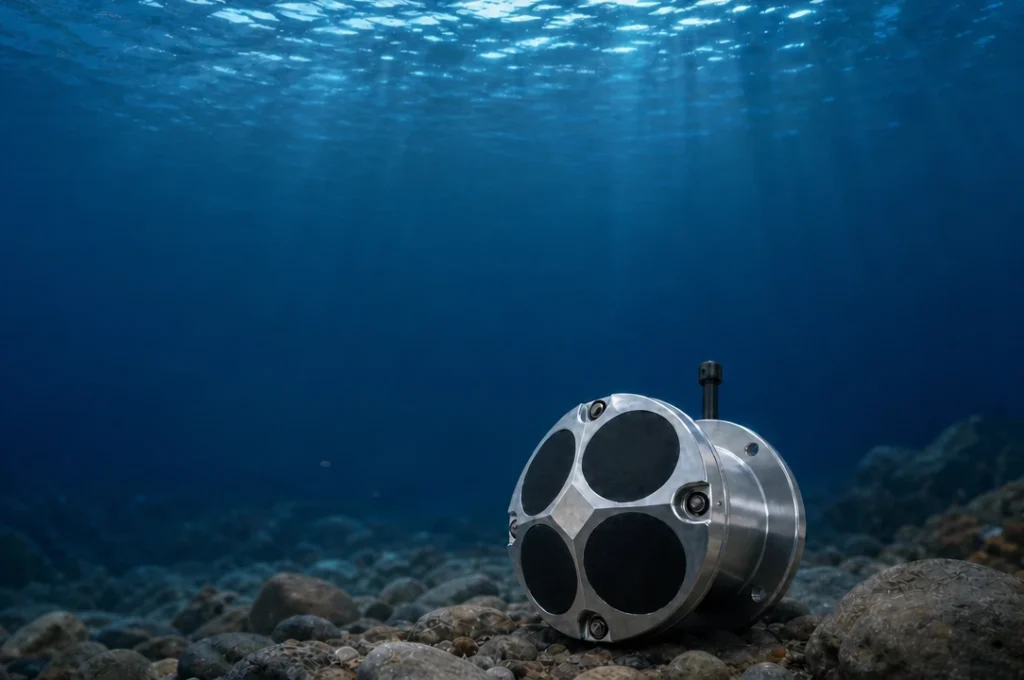
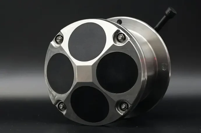
A DVL mounts on the underside of the vehicle and transmits four acoustic beams downward in a Janus configuration: one forward, one aft, one port, one starboard. Each beam is angled approximately 20°–30° from vertical.
These beams hit the seafloor and reflect back. Because the vehicle is moving relative to the seafloor, the reflected signal’s frequency is shifted by the Doppler effect — the same physics that makes an ambulance siren sound higher-pitched as it approaches you and lower as it drives away.
The DVL measures the frequency shift on each of the four beams. The shift is proportional to the vehicle’s velocity component along that beam’s direction. With four independent measurements, the system solves for 3D velocity:
- Surge — forward/backward velocity (fore beam vs aft beam)
- Sway — sideways velocity (port beam vs starboard beam)
- Heave — vertical velocity (all four beams averaged)
Additionally, by measuring the time it takes for each acoustic pulse to make the round trip, the DVL calculates altitude above the seafloor.
DVL Frequency Selection
The DVL’s operating frequency determines its altitude range — a fundamental trade-off between range and resolution:
| Frequency | Typical Altitude Range | Best Application | Size / Power |
|---|---|---|---|
| 1200 kHz | 0.2–30 m | Small ROVs, shallow inspection, harbor ops | Compact, ~3–8W |
| 600 kHz | 0.5–100 m | Mid-size AUVs, coastal surveys, pipeline inspection | Balanced, ~5–15W |
| 300 kHz | 1–200 m | Deep-water AUVs, offshore energy, long-range missions | Larger, ~10–30W |
| 150 kHz | 5–400+ m | Full ocean depth vehicles | Largest, highest power |
Phased-Array vs Piston Transducers
Traditional DVLs use piston transducers — individual ceramic elements, each mechanically aimed at the required beam angle. This works, but it imposes physical constraints: the transducers need space, they’re relatively heavy, and they consume significant power.
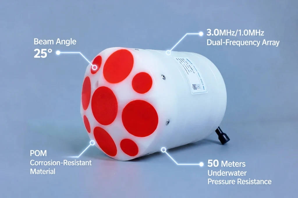
Phased-array DVLs use a flat array of many small elements. By precisely timing the electrical signals to each element, the beam is steered electronically — no mechanical angling required. The advantages are significant: smaller form factor, lower weight, lower power consumption (typically 3–5W vs 15–30W for piston designs). For battery-powered AUVs on long missions, this power difference directly translates to longer endurance. As a concrete example, the Oceantek DVL-600-PA5 — a phased-array design — achieves ±0.3% velocity accuracy at 5W, a smaller size than a comparable piston-transducer DVL.
Bottom Track vs Water Track
All DVLs have two operating modes:
- Bottom tracking measures velocity relative to the seafloor. This is the primary navigation mode — it gives true ground-referenced velocity. But it only works when the vehicle is within the DVL’s altitude range.
- Water tracking measures velocity relative to the water column at a set distance from the vehicle — typically 5–15 meters ahead. Used when the vehicle is too high above the bottom for bottom lock, or when operating mid-water. Less accurate than bottom tracking, but better than nothing.
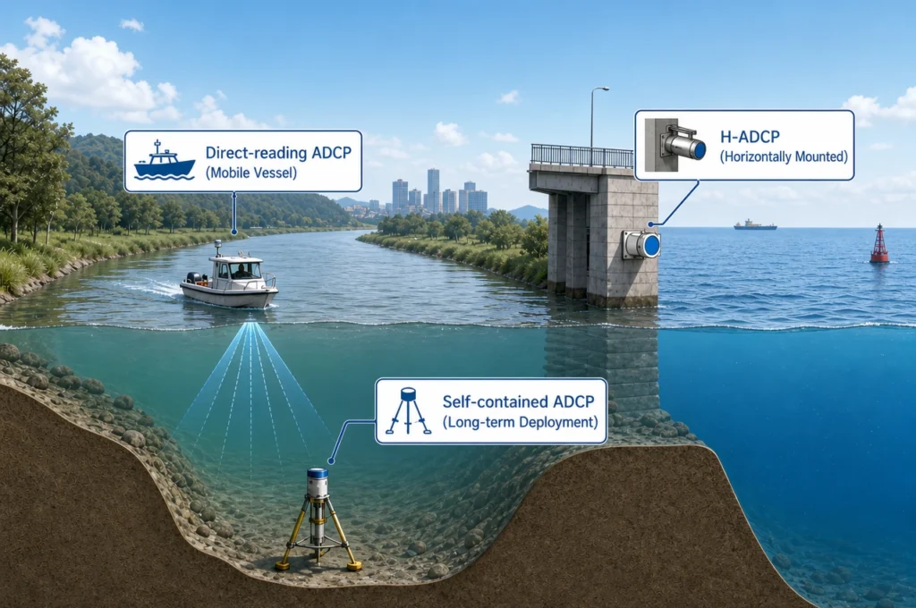
Most DVLs also support an ADCP mode (Acoustic Doppler Current Profiler), which profiles water current velocities at multiple depth cells. This is a secondary function — the same hardware doing a different job — and useful when the vehicle also needs to measure ocean currents during its mission.
6. INS — Inertial Navigation System
How It Works
An INS takes a fundamentally different approach from everything we’ve discussed so far. It doesn’t interact with the outside world at all — it measures the vehicle’s own motion from the inside.
Inside an INS are two sensor triads:
- Three accelerometers — one each for the X, Y, and Z axes. They measure linear acceleration: any change in the vehicle’s velocity along any axis.
- Three gyroscopes — one each for roll, pitch, and yaw. They measure angular rotation rate: any change in the vehicle’s orientation.
From a known starting position and orientation, the INS continuously integrates these measurements:
- Integrate angular rate once → current orientation (roll, pitch, heading)
- Integrate acceleration once → current velocity (after accounting for gravity)
- Integrate velocity once → current position
The Drift Problem
Every integration step accumulates error. A tiny bias in an accelerometer — say 10 micrograms (10 μg, or 0.0001 m/s²) — seems negligible. But integrate that bias over one hour:
Position error = ½ × bias × time²
= ½ × (0.0001 m/s²) × (3600 s)²
= 648 meters of position error — from a 10 μg bias
This is why an unaided INS is useless for underwater navigation. It drifts — and the drift grows quadratically with time.
| INS Grade | Accelerometer Bias | Unaided Drift (1 hr) | Typical Platform |
|---|---|---|---|
| Tactical (MEMS) | 10–100 μg | ~1–10 km | Small ROVs, consumer AUVs |
| Navigation-grade (FOG/RLG) | 0.1–1 μg | ~100–500 m | Professional AUVs, military submarines |
| Strategic-grade | < 0.01 μg | < 50 m | Strategic submarines, ICBM guidance |
Why INS Still Matters
If INS drifts so badly alone, why is it still a core component of every underwater navigation system? Three reasons:
- Update rate — INS updates at 100–400 Hz. USBL updates at 0.5–2 Hz. Between acoustic fixes, the INS is the only thing filling the gap.
- Self-contained — INS works at any depth, in any water condition, with no external signals. It can’t be jammed, shadowed, or interrupted.
- Orientation — INS provides roll, pitch, and heading, which are needed to interpret every other sensor’s measurements correctly.
The INS isn’t the star of the show — it’s the backbone. It provides the high-rate, uninterrupted motion estimate that other sensors then correct.
7. Sensor Fusion: How It All Works Together
No single sensor solves underwater positioning. The art is in combining them so each compensates for the weaknesses of the others.
The Kalman Filter
At the center of every modern underwater navigation system runs a Kalman filter — a mathematical algorithm that optimally combines multiple noisy measurements to produce a single best estimate. It works in two steps, repeated continuously:
- Predict: The INS says “based on the acceleration and rotation I’ve measured since the last update, I predict the vehicle is now at position X₁”
- Update: An external measurement arrives — a USBL position fix, or a DVL velocity reading. The filter compares the prediction to the measurement, weights each by its known uncertainty, and produces a corrected estimate.
The filter knows how much to trust each sensor because each sensor’s noise characteristics are modeled in advance. A USBL fix at 2,000 meters range gets less weight than one at 100 meters. A DVL velocity measurement over a hard rocky bottom gets more weight than one over soft sediment. The INS prediction gets more weight immediately after a USBL fix and less weight as time since the last fix grows.
The Navigation Loop in Practice
Here’s what actually happens during a typical AUV mission:
- Surface (t=0): Vehicle gets a GPS fix. Absolute position is known. The Kalman filter initializes.
- Descent: INS tracks downward motion. Once within DVL range, the DVL acquires bottom lock and starts feeding velocity data. Pressure sensor gives depth.
- Mission cruise: DVL + INS run in tight integration. The DVL updates at 4–8 Hz — every 0.125–0.25 seconds, the filter corrects INS drift with a fresh velocity measurement. Position error stays tightly bounded.
- USBL fix (periodic): Every few seconds to minutes, a USBL position fix arrives from the surface vessel. This provides an absolute position reference that resets any accumulated dead-reckoning drift.
- Acoustic dropout: If the vessel maneuvers sharply or the vehicle enters an acoustic shadow (behind a structure or in a thermocline), USBL updates stop. The DVL + INS combination carries the navigation solution through the gap.
- Surfacing: Final GPS fix confirms total navigation drift. For a well-integrated system: 0.05–0.1% of distance traveled.
The Component Hierarchy
Not all components contribute equally. Here’s the rough hierarchy of importance in a DVL-aided INS navigation system:
| Component | What It Prevents | Failure Consequence |
|---|---|---|
| DVL | INS velocity drift (linear growth) | Position error grows to kilometers within minutes |
| INS | Gaps between external fixes | No navigation between USBL updates (seconds of blindness) |
| USBL | DVL dead-reckoning drift (unbounded) | Position error grows to 0.05–0.1% of distance (acceptable for some missions) |
| Pressure sensor | Depth uncertainty | Depth error of a few meters (usually acceptable; Z is the easy axis) |
Notice this: you can complete a mission without USBL if your DVL + INS is good enough (many AUVs do exactly this, surfacing periodically for a GPS fix). But you cannot complete a mission with USBL + INS if your DVL fails — the position uncertainty between fixes grows too fast.
8. Technology Comparison at a Glance
| Factor | USBL | LBL | DVL | INS (alone) |
|---|---|---|---|---|
| Absolute Position | Yes ★★★ | Yes ★★★ | No | No |
| Accuracy | 0.1–0.5% range ★★ | 1–15 cm ★★★ | ±0.05–0.5% vel ★★★ | Drifts rapidly ★ |
| Update Rate | 0.5–2 Hz ★ | 0.1–1 Hz ★ | 1–8 Hz ★★★ | 100–400 Hz ★★★ |
| Ease of Deployment | Easy ★★★ | Complex ★ | Vehicle-mounted ★★★ | Vehicle-mounted ★★★ |
| Deep Water | Good ★★ | Excellent ★★★ | Freq-limited ★★ | Depth-independent ★★★ |
| Multi-Vehicle Capable | Limited ★★ | Unlimited ★★★ | Unlimited ★★★ | Unlimited ★★★ |
9. Real-World Applications
Offshore Energy
Pipeline inspection ROVs use USBL + DVL to maintain position while scanning kilometers of pipeline. Offshore wind farm construction requires precise positioning for cable laying, foundation installation, and turbine placement. A single project may operate 3–5 ROVs simultaneously, each needing independent positioning. For deep-water construction, LBL arrays provide the centimeter-level accuracy required to mate subsea structures.
Defense & Security
Mine countermeasure AUVs need positioning accurate enough to re-acquire and neutralize individual targets. Military submarines rely on INS + DVL for covert navigation — any acoustic transmission (USBL or LBL interrogation) would reveal their position. Special forces diver delivery vehicles use compact USBL/DVL systems for covert infiltration in shallow coastal waters.
Marine Science
Scientific AUVs conducting seafloor mapping need precise positioning to georeference multibeam sonar data. Hydrothermal vent researchers must be able to revisit specific vent chimneys years apart — LBL arrays left on the seafloor make this possible. Underwater archaeologists use LBL to create millimeter-accurate 3D site maps of shipwrecks.
Search & Recovery
Black box recovery after aircraft accidents uses USBL to guide deep-water ROVs to the underwater locator beacon. Salvage operations require precise positioning to rig lifting equipment. Search and rescue teams use side-scan sonar towfish with USBL positioning to systematically cover large search areas without gaps or overlaps.
Civil Infrastructure
Dam inspection ROVs use DVL for station-keeping in turbulent near-dam environments. Bridge scour monitoring deploys bottom-mounted ADCP/DVL instruments to measure sediment transport. Submarine cable route surveys require accurate positioning to plan cable lay paths and document as-built positions.
10. How to Choose an Underwater Positioning System
The right system depends on answering five questions. Work through them in order:
Question 1: What’s your operating depth?
| Depth Range | Recommended Approach |
|---|---|
| < 30 m | Portable USBL + 1200 kHz DVL. Low cost, simple deployment. |
| 30–200 m | Mid-frequency USBL + 600 kHz DVL. Most common commercial configuration. |
| 200–1,000 m | Low-frequency USBL + 300 kHz DVL. Consider LBL for construction. |
| > 1,000 m | High-power USBL or LBL + deep-rated 300/150 kHz DVL. Phased-array preferred for power efficiency. |
Question 2: How much accuracy do you actually need?
| Requirement | System | Example Use |
|---|---|---|
| < 20 m acceptable | DVL + compass only (no USBL) | Recreational ROV, basic visual surveys |
| 1–5 m | USBL + DVL + INS (standard integration) | Pipeline inspection, environmental monitoring |
| 0.1–1 m | USBL + high-grade DVL + nav-grade INS | Offshore construction, mine countermeasures |
| < 10 cm | LBL + DVL + INS (tight integration) | Deep-water construction, wreck mapping |
Question 3: What’s your budget?
| Budget Tier | What You Get | Typical Configuration |
|---|---|---|
| $2K–$10K | Portable USBL, < 100 m range | Water Linked UGPS G2 + GPS buoy |
| $15K–$50K | Mid-range DVL with bottom tracking | 600 kHz DVL + INS integration kit |
| $50K–$150K | Complete USBL + DVL + INS, professional | Vessel USBL + phased-array DVL + nav-grade INS |
| $150K–$500K+ | Industrial LBL array + full deep-water suite | LBL array (5 transponders) + deep-water navigation suite |
Question 4: Single vehicle or multiple?
- Single vehicle: USBL is the practical choice. One transceiver, one transponder.
- Multiple vehicles simultaneously: LBL scales better. Once the seabed array is deployed, any number of vehicles can navigate within it. USBL can track multiple transponders but they share the same acoustic channel bandwidth — update rate per vehicle drops as you add more.
Question 5: What’s your power budget and mission duration?
For battery-powered AUVs on missions lasting 8–72 hours, every watt counts. A traditional piston-transducer DVL draws 15–30W continuously. A phased-array DVL draws 3–5W. Over a 24-hour mission, that’s 72 Wh versus 360 Wh — the difference between a smaller battery pack and a larger one, or between an extra 50 km of range and having to surface early.
11. Frequently Asked Questions
Does GPS work underwater?
No. GPS radio waves at 1.5 GHz are absorbed by water within centimeters — this is physics, not a limitation we can engineer around. All underwater positioning uses acoustic signals (sound waves) instead, which travel tens of kilometers through seawater.
What replaces GPS underwater?
A combination of acoustic positioning (USBL or LBL for absolute position fixes), a Doppler Velocity Log (for velocity-over-ground), an Inertial Navigation System (for continuous dead reckoning between fixes), and a pressure sensor (for depth). A Kalman filter fuses all four into a single navigation solution.
How accurate is underwater positioning?
LBL: 1–15 cm (centimeter-level). USBL: 0.1–0.5% of slant range (e.g., ±0.5 m at 100 m depth, ±5 m at 1,000 m). DVL-aided INS: 0.05–0.1% of distance traveled (5–10 m drift over a 10 km mission). These technologies are typically used together, with sensor fusion improving the combined result.
What is a DVL?
A Doppler Velocity Log is an acoustic sensor that measures a vehicle’s 3D velocity relative to the seafloor. It transmits four beams in a Janus configuration and measures the Doppler frequency shift of each reflected beam. This is the sensor that prevents INS drift from growing unbounded during underwater missions.
What’s the difference between ADCP and DVL?
An ADCP (Acoustic Doppler Current Profiler) measures water current velocity at multiple depths — it profiles the water column. A DVL measures the vehicle’s own velocity relative to the seafloor — it navigates the vehicle. Many modern instruments can do both, but their primary design purposes are different: ADCP = measuring the ocean, DVL = navigating through it.
How much does underwater positioning cost?
Portable USBL systems start around $2,000–$5,000. Mid-range DVLs cost $15,000–$50,000. Complete professional USBL + DVL + INS systems run $50,000–$150,000. Full industrial LBL arrays with deep-water navigation suites can exceed $500,000.
Can ROVs and AUVs use GPS?
They cannot use GPS while submerged. ROVs typically rely on USBL tracking from the surface vessel. AUVs surface periodically to get a GPS fix, then navigate underwater using DVL + INS dead reckoning between surface intervals. Some hybrid systems use a surface buoy that relays GPS position to the vehicle acoustically.
Do I need both USBL and DVL?
For professional operations: yes, you typically need both. USBL provides periodic absolute position fixes that reset accumulated drift. DVL provides continuous velocity between fixes. Without DVL, position error diverges rapidly between USBL updates. Without USBL, DVL dead reckoning accumulates unbounded drift. The one exception: short-range AUV missions where the vehicle surfaces frequently for GPS — in that case, DVL + INS alone may be sufficient.
Why does sound speed vary underwater?
Sound speed in seawater depends on temperature (dominant factor in the upper ocean), salinity, and pressure (dominant at depth). A 1°C temperature change shifts sound speed by roughly 4 m/s. Over a 2,000-meter acoustic path, that’s enough error to throw off a range measurement by several meters. This is why serious operations deploy a sound velocity profiler (SVP) at the start of each mission — the actual sound speed profile must be measured, not assumed.
Research Methodology: This guide draws on peer-reviewed literature in underwater acoustics and inertial navigation, published specifications from major underwater positioning system manufacturers (Sonardyne, Kongsberg, iXblue, Teledyne, Water Linked), and practical deployment experience across AUV, ROV, and subsea survey applications.
Disclosure: OceanADCP is a brand of Oceantek Marine Technology. Oceantek manufactures DVL and ADCP instruments, including phased-array models discussed in this article. All technology comparisons are based on publicly available specifications and independent third-party test data.
© 2026 Ocean (Hangzhou) Technology Co., Ltd.,All rights reserved. Last updated: August 3, 2026.