In acoustic Doppler current profiling, the real challenge isn’t emitting sound waves — it’s stably forming beams in a specified direction, accurately identifying weak frequency shifts in return echoes, and reliably converting multiple radial velocities into a three-dimensional flow velocity profile.
That’s exactly where phased array ADCP technology excels.
Unlike traditional ADCPs that rely on fixed-angle transducers, phased array ADCPs are built on multi-element planar arrays. By coordinately controlling the phase, time delay, and amplitude of each element, they synthesize transmit and receive beams in target directions. This doesn’t just change the instrument’s physical structure — it fundamentally reconstructs the measurement geometry and signal processing chain.
The value of phased array ADCPs, therefore, isn’t merely smaller size or easier installation. It’s about transforming beam geometry — once dictated by mechanical structures — into designable, calibratable, and verifiable array beams. Beam pointing angle, beam width, symmetry, sidelobe levels, and channel consistency all become engineering-controllable parameters.
1. The Essence of Phased Arrays — Coherent Element Superposition Creates Steerable Beams
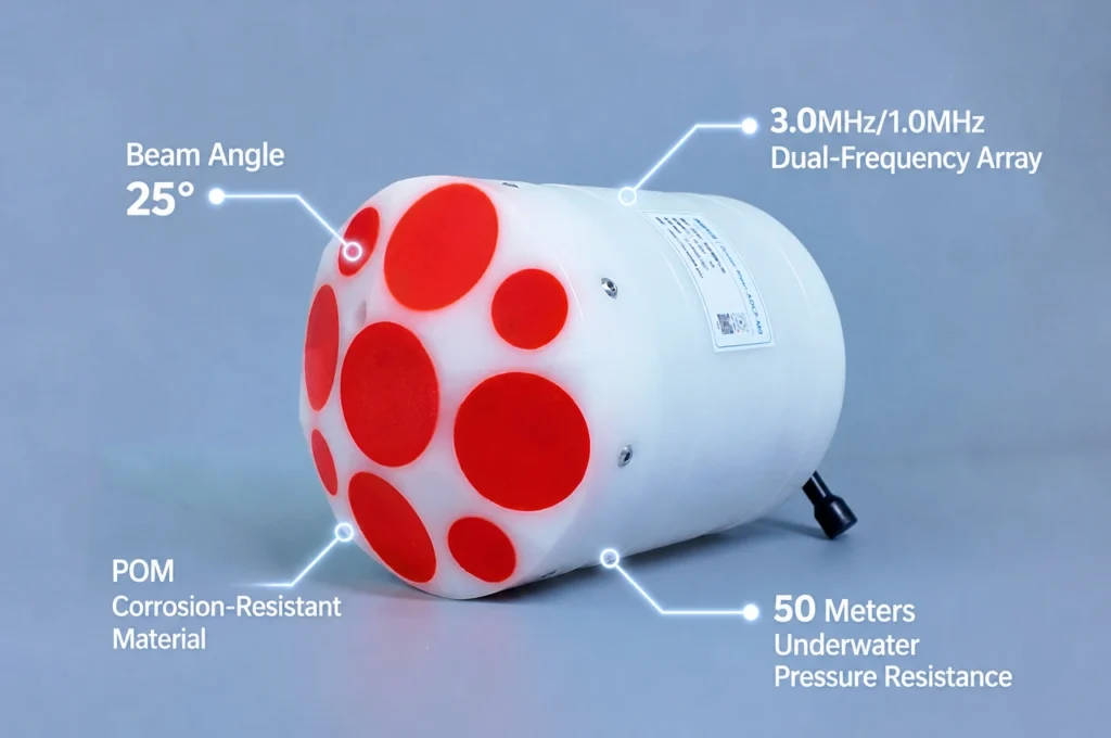
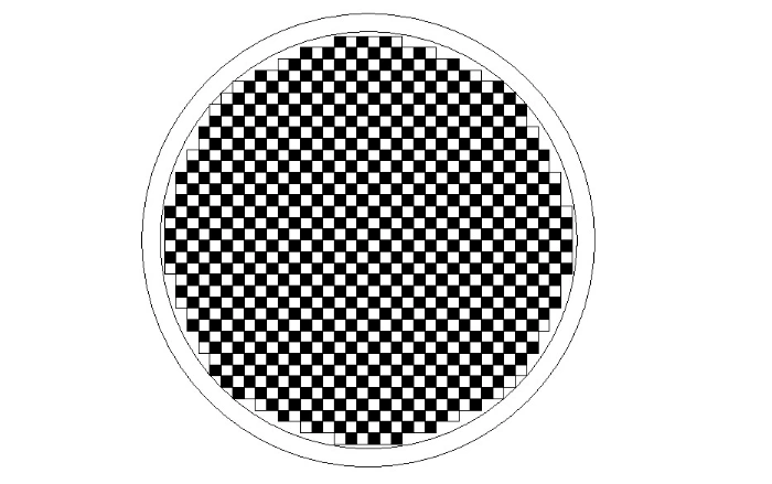
Phased array ADCPs typically use circular or near-circular planar arrays. The array face consists of multiple small transducer elements, each transmitting or receiving acoustic signals according to predetermined phase, time delay, and amplitude relationships.
When the compensation relationship between elements matches the acoustic path difference in the target direction, sound wave energy in that direction achieves coherent superposition, forming the main lobe. Signals in non-target directions, unable to achieve perfect phase alignment, undergo partial cancellation.
From a signal processing perspective, array beam forming isn’t simply stacking multiple signals — it’s a spatially selective filtering process. Element positions, element spacing, phase compensation, time delay compensation, amplitude weighting, and channel consistency all influence the final beam pattern.
This is the key distinction between phased array ADCPs and traditional fixed-transducer ADCPs:
- Traditional structures rely primarily on mechanical mounting angles to form beams
- Phased array structures form beams through array control relationships
The former depends more on mechanical geometric precision; the latter extends beam control across the complete chain of array design → electronic channels → digital processing → system calibration.
2. Beam Geometry Determines the Condition Number of Velocity Inversion
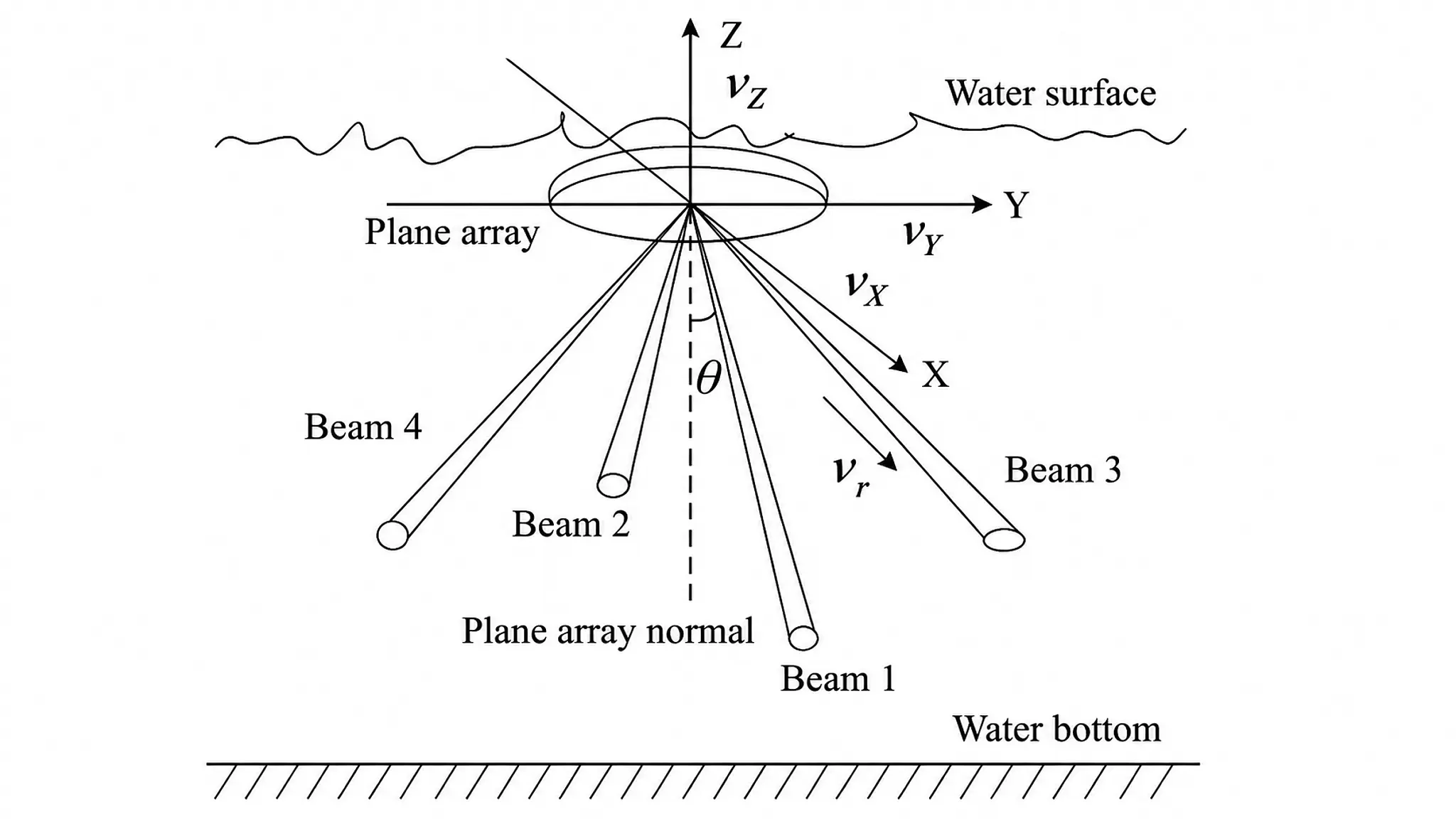
Each measurement beam captures the projected velocity of water flow along that beam’s direction. Only through geometric transformation can multiple radial velocities yield a 3D flow vector.
The process can be summarized as:
Vb = H·V + e
Where:
- Vb — radial velocity vector measured by each beam
- V — the unknown 3D flow velocity vector
- H — observation matrix composed of beam angles, beam directions, and mounting geometry
- e — composite error term including frequency measurement errors, beam deviations, attitude errors, and environmental disturbances
This means beam angle, beam direction, and beam symmetry aren’t merely structural parameters — they enter the velocity inversion equation as measurement conditions.
When beam geometry is stable and symmetric, radial velocities form better complementary relationships. When a beam shows significant deviation, abnormal beam width, or inconsistent response, errors can be amplified through vector inversion, ultimately manifesting as biases in horizontal velocity, vertical velocity, or flow direction.
The core goal of a phased array ADCP, therefore, is not simply “forming multiple acoustic beams” — it’s forming a set of beams with well-defined geometry, stable pointing, consistent response, and the capacity to support reliable inversion.
3. Three Design Constraints for Phased Array ADCPs
Phased array ADCP design revolves around three core variables:
- Element spacing
- Effective aperture
- Element weighting and array structure
3.1 Element Spacing: Determines Grating Lobe Risk
When element spacing is too large, grating lobes can appear during oblique transmission or reception. Grating lobes are “false directions” outside the main lobe that introduce non-target echoes, contaminating current measurement results.
Engineering practice typically limits element spacing to no more than half a wavelength to reduce grating lobe probability, while balancing array face dimensions and implementation complexity.
3.2 Effective Aperture: Determines Main Lobe Width
A larger effective aperture generally produces a narrower, more directive main lobe — but also increases array complexity, structural demands, installation requirements, and power consumption.
- Overly wide main lobe → reduced resolution, easier echo aliasing
- Overly narrow main lobe → increased control difficulty, higher sensitivity to attitude and array consistency
Aperture design must be determined holistically based on measurement range, beam angle, platform space, and signal architecture — not by simply pursuing “bigger” or “narrower.”
3.3 Sidelobe Level: Determines Non-Target Echo Suppression
Sidelobes are energy leakage outside the main lobe. When sidelobe levels are too high, echoes from boundaries or strongly reflective regions can enter measurement cells and affect velocity results.
This effect is more pronounced near the bottom, near the surface, or in structurally complex areas, degrading data quality. In practice, due to element inconsistencies, manufacturing tolerances, and other factors, sidelobes often exceed theoretical values and may vary between beams.
4. Phase-Shift Beam Forming vs. Time-Delay Beam Forming
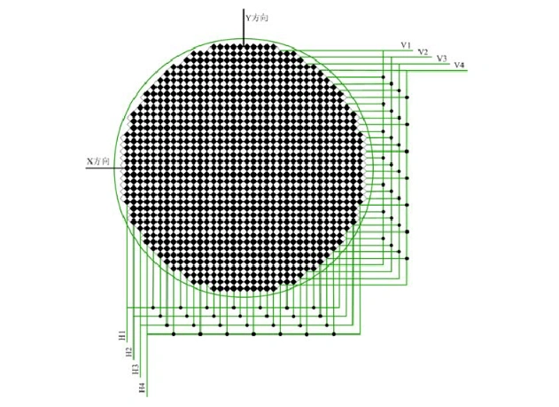
Phased array beam forming primarily uses two methods: phase-shift beam forming and time-delay beam forming.
For narrowband signals, the two are approximately equivalent near the center frequency. The relationship between inter-element phase shift β and time delay τ is:
β = 2πf₀τ
In this case, fixed phase shifts adequately compensate for inter-element phase differences — and implementation is relatively straightforward.
However, under wideband coded signal conditions, fixed phase shifts cannot simultaneously apply to all frequency components. Since phase shift varies with frequency, different frequency signals experience varying degrees of beam deviation — known as beam squint.
From a signal perspective, this degrades code alignment in both time and frequency, manifesting as energy dispersion, uneven signal attenuation, and ultimately affecting beam pointing, signal-to-noise ratio, and Doppler frequency measurement accuracy.
Time-delay beam forming, by contrast, directly compensates for propagation time differences. It’s better suited to wideband signals and produces more stable beam pointing — but requires more control channels, making system implementation more complex and costly.
| Method | Narrowband | Wideband | Complexity | Beam Stability |
|---|---|---|---|---|
| Phase-Shift | ✓ Good | ✗ Beam squint | Lower | Frequency-dependent |
| Time-Delay | ✓ Good | ✓ Excellent | Higher | Frequency-independent |
The choice between these methods depends on bandwidth, coding scheme, SNR requirements, and system complexity constraints.
5. Phased Array ADCP Data Reliability — Start With “Beam Quality”
A smooth, continuous velocity profile curve doesn’t automatically prove data trustworthiness.
For phased array ADCPs, data reliability must be established across at least the following layers:
5.1 Array Layer
Element consistency, channel gain, phase stability, beam pattern, main lobe width, sidelobe level, and inter-beam symmetry.
5.2 Signal Layer
Echo intensity, correlation, signal-to-noise ratio, spectral stability, anomalous frequency shifts, and percentage of valid samples.
5.3 Geometric Layer
Beam pointing, beam angle, mounting offset, attitude data, and coordinate transformation relationships.
5.4 Inversion Layer
Consistency between radial velocities, vector inversion residuals, vertical velocity anomalies, continuity across adjacent depth cells, and outlier ratio.
5.5 Engineering Verification Layer
Closed-loop validation of system capability through tank beam pattern tests, still-water zero-velocity tests, tow-tank trials, standard flow field comparisons, repeat field observations, and long-term stability testing.
6. Oceantek — Deep Expertise in Phased Array ADCP
For Oceantek, phased array ADCP is not simply a transducer structure change. It’s a systems technology spanning array acoustics, transmit/receive chains, signal processing, attitude correction, and velocity computation.
In phased array ADCP development, Oceantek focuses not only on device miniaturization and integration capability, but on the overall synergy between element consistency, beam forming, transmit/receive stability, and data processing with quality control.
The R&D priorities center on several critical questions:
- Are beams stably pointed toward target directions?
- Are elements and channels consistently matched?
- Are beam errors controllable under different signal conditions?
- Can attitude and mounting variations be effectively corrected?
- Is data reliable across different water column conditions?
The Future of Current Measurement
As marine and engineering applications demand increasingly stable and verifiable flow field data, phased array technology will continue to advance.
Oceantek, as a benchmark manufacturer in China’s ADCP industry, continues to drive R&D and application of phased array current measurement technology, with products deployed across diverse and complex water environments.
Interested in phased array ADCP solutions for your application? Contact Oceantek to learn more about our product lineup and technical capabilities.