Every Doppler Velocity Log (DVL) aboard an underwater vehicle runs two measurement modes simultaneously — bottom tracking and water tracking. One tells the vehicle where it is going. The other tells it what the water is doing. Confuse the two, and your navigation solution falls apart. This article explains how each mode works, when each dominates, and why a DVL that excels at both is the difference between a clean survey and a wasted deployment.
The Core Problem: A Moving Platform in a Moving Medium
Picture an AUV cruising at 1,000 meters depth. It needs to know its position. GPS is unavailable — radio waves don’t penetrate seawater. Inertial navigation drifts. The DVL is the primary velocity sensor, firing four acoustic beams toward the seafloor and measuring the Doppler shift of the returned echo.
But the DVL receives two distinct echoes from every ping:
- Bottom echo — reflected off the seabed. This tells you the vehicle’s velocity relative to the Earth.
- Water-column echo — scattered back by suspended particles, plankton, and bubbles at multiple ranges. This tells you the velocity of the water relative to the vehicle at each depth layer.
The bottom echo gives you navigation. The water-column echo gives you oceanographic data. A DVL processes both — and the smartest navigation systems fuse the two.
What Is Bottom Tracking?
Bottom tracking is the DVL’s primary navigation mode. The instrument transmits an acoustic pulse toward the seafloor, measures the Doppler frequency shift of the returning echo, and converts that shift into a three-dimensional velocity vector.
Because the seabed is stationary, the measured velocity equals the vehicle’s absolute velocity over ground. Integrate that velocity over time, and you have position — the fundamental input to any subsea inertial navigation system (INS).
How Bottom Tracking Works, Step by Step
- Transmit: The DVL sends a short acoustic pulse (typically 300 kHz or 600 kHz) along each of its four beams, angled 20–30° from vertical in a Janus configuration.
- Propagate: The pulse travels through the water column to the seafloor. The round-trip time gives you the range to bottom.
- Reflect: The pulse scatters off the rough seabed surface. Unlike a flat mirror, the seabed is a diffuse scatterer — it sends acoustic energy back in many directions, and enough returns along the beam axis for the DVL to detect.
- Receive: The transducer picks up the bottom-reflected echo. The received frequency differs from the transmitted frequency by an amount proportional to the relative velocity between the vehicle and the seabed along each beam.
- Compute: The DVL’s signal processor estimates the Doppler shift on each beam, converts the four beam-axial velocities into a 3D velocity vector (east, north, up), and outputs the result — typically at 1–2 Hz.
The key word is absolute. Bottom-track velocity is the gold standard for subsea navigation because it is referenced to a stationary frame. No drift. No cumulative error from water currents. Just vehicle speed over ground, measured directly.
What Is Water Tracking?
Water tracking measures the Doppler shift from scatterers suspended in the water column — sediment particles, plankton, microbubbles, and density microstructure — at multiple ranges simultaneously. Instead of one bottom echo, the DVL receives a continuous stream of backscatter from every depth layer the pulse traverses.
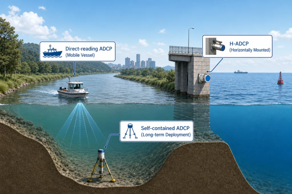
The result is a velocity profile: current speed and direction as a function of distance from the transducer. This is the same principle that makes an ADCP (Acoustic Doppler Current Profiler) work — and indeed, every DVL with water-tracking capability is effectively a navigation-grade ADCP.
How Water Tracking Works, Step by Step
- Transmit: Same pulse as bottom tracking — the DVL doesn’t transmit separate pings for the two modes. One ping serves both.
- Range-gate: The receiver opens at precise time windows, each corresponding to a specific depth layer (called a “depth cell” or “bin”). A typical DVL might divide the water column into cells of 1–8 meters, stacking 20–80 cells from the transducer face to the seafloor.
- Receive per cell: For each depth cell, the DVL measures the Doppler shift of the backscattered energy arriving during that cell’s time window.
- Compute per cell: The four-beam velocity is solved for each cell independently, yielding an east-north-up velocity at every depth.
- Subtract vehicle motion: If the vehicle is moving (and it always is), the water-track velocities must be corrected by subtracting the bottom-track velocity. The result is absolute water current — what the ocean is actually doing, independent of platform motion.
Water tracking gives you the oceanographic picture. But it also serves as a navigation fallback — when the bottom is out of range, the DVL can still measure its velocity relative to a water layer. It’s not as good as bottom lock, but it’s far better than nothing.
Bottom Tracking vs Water Tracking: The Key Differences
| Feature | Bottom Tracking | Water Tracking |
|---|---|---|
| Reference frame | Earth-fixed (seabed) | Water-relative (moving scatterers) |
| Primary output | Vehicle velocity over ground | Water current profile vs. depth |
| Navigation quality | Absolute — no cumulative drift | Relative — drifts with unknown water motion |
| Range limit | Water depth & acoustic frequency (e.g., ~120 m at 600 kHz) | Water-column backscatter strength (e.g., 55–70 m at 600 kHz) |
| Minimum depth | 0.8–2.0 m (blanking zone dependent) | 0.5–1.0 m from transducer face |
| Failure mode | Loss of bottom lock (too deep, too soft a seabed, too steep a slope) | Low backscatter (clear water, few scatterers) |
| Data rate | 1–2 Hz (single velocity vector) | 1–2 Hz (velocity profile, up to 100+ cells) |
| Integration target | Inertial Navigation System (INS) | CTD, ADCP data chain, oceanographic models |
| Accuracy driver | Sound speed at transducer face, beam geometry, seabed slope | Scatterer distribution, turbulent fluctuations, acoustic SNR |
The Janus Configuration: Why Four Beams Make Both Modes Work
Both bottom tracking and water tracking rely on the DVL’s Janus beam geometry — four transducer elements pointed in orthogonal directions, each tilted 20–30° from vertical. This configuration solves a fundamental problem: a single beam only measures velocity along its own axis. You need at least three beams to reconstruct a 3D velocity vector, and a fourth beam provides redundancy and error-velocity diagnostics.
The Janus configuration also cancels certain biases. If the instrument tilts — and it always does on a moving vehicle — the velocity error introduced on one beam is partially canceled by the geometrically opposite beam. This self-correcting property is why the Janus configuration has been the industry standard since the 1970s, applied to both ADCPs and DVLs.
When Bottom Tracking Fails: Three Real-World Scenarios
Bottom tracking is the preferred navigation reference — but it’s not always available. Experienced operators recognize three common failure modes:
1. Beyond Bottom-Track Range
Every DVL has a maximum bottom-tracking depth determined by its acoustic frequency and transmitted power. A 600 kHz DVL typically tracks bottom to ~120 m; a 300 kHz unit can reach 200–300 m. When the vehicle operates deeper than this limit, the bottom echo is too weak to detect. The DVL loses bottom lock.
The fallback: Water-track velocity from a deep, presumably stationary water layer. The INS integrates this water-relative velocity while adding a drift term to account for unknown current. Navigation quality degrades — typically from meter-level to tens-of-meters-level error per hour.
2. Steep or Rough Topography
DVLs assume a flat, horizontal seabed. When the vehicle flies over a steep slope, canyon wall, or rugged terrain, the bottom echo returns from an unpredictable geometry. The range to bottom differs across the four beams, and the Doppler shift is contaminated by the local slope angle. The DVL may report a plausible velocity that is wrong by 5–20%.
The fallback: If the DVL’s internal quality metrics flag the bottom solution as degraded, the navigation filter should down-weight bottom track and blend in water-track data from a stable layer — or rely more heavily on the INS during the terrain passage.
3. Soft or Fluid Seabed
Mud, fluidized sediment, and thick flocculent layers (common in deep-ocean basins and river deltas) make poor acoustic reflectors. The bottom echo may be too weak or too diffuse for the DVL to extract a clean Doppler estimate. The instrument may report “bottom lock” intermittently while producing noisy, unreliable velocities.
The fallback: Same as the deep-water case — switch to water-track referencing and accept increased navigation drift until a solid bottom return is reacquired.
When Water Tracking Becomes the Primary Sensor
In some missions, water tracking isn’t a fallback — it’s the whole point of the deployment:
- Oceanographic surveys: A research vessel deploys a ship-hull ADCP/DVL to measure current structure from the surface to 1,000 m. Bottom track is only used to correct the ship’s own velocity — the scientific product is the water-column profile.
- Submesoscale feature tracking: Autonomous underwater gliders and profiling floats use water-track velocity to map eddies, fronts, and internal waves at scales too fine for satellite altimetry.
- Mid-water AUV navigation: When an AUV transits between survey areas at constant depth far above the seafloor, water tracking provides a velocity reference. The INS models the unknown mid-water current as a slowly varying bias and corrects for it during bottom-locked survey legs.
- Discharge measurement: In rivers and estuaries, a vessel-mounted ADCP/DVL uses bottom tracking for vessel velocity and water tracking to profile the river’s flow field. The combination yields total discharge — the core measurement of hydrometry.
How Oceantek DVL Handles Both Modes
The physical principle is the same for every DVL. The difference is in the engineering. Oceantek’s DVL platform processes bottom-track and water-track echoes through a shared acoustic front-end but separate signal-processing chains:
- Bottom-track processor: Optimized for a single strong echo at variable range. Runs a high-resolution delay-locked loop to track the bottom echo’s time-of-arrival jitter — critical for maintaining lock in rough terrain and during vehicle pitch/roll maneuvers.
- Water-track processor: Range-gated across up to 128 depth cells simultaneously. Each cell runs an independent Doppler estimator. The processor dynamically allocates ping energy across cells — fewer cells in shallow water for faster update rates, more cells in deep water for full-profile coverage.
- Adaptive mode switching: When bottom-track quality (correlation, amplitude, and velocity-consistency metrics) drops below threshold, the navigation output automatically blends in water-track data from the deepest valid cell — typically 10–20 meters above the seabed where currents are assumed weak and stable.
The DVL vs ADCP distinction largely comes down to this dual-mode design. An ADCP is optimized for water-column profiling and treats bottom tracking as a secondary feature. A DVL is optimized for bottom-referenced navigation and treats water tracking as a secondary data product. In practice, a well-designed DVL does both well — and the user decides which mode drives the mission.
Real-world performance data illustrates the point: during the DVL-600K Qiandao Lake test, the Oceantek 600 kHz DVL maintained simultaneous bottom lock and water-column profiling across depths from 2 m to 85 m, with the bottom-track velocity showing agreement within 0.3% of differential GPS reference.
Practical Guidelines: Choosing and Operating the Right Mode
| Your Mission | Primary Mode | Critical Spec to Check |
|---|---|---|
| AUV seafloor survey (< 100 m depth) | Bottom tracking | Bottom-track range, minimum blanking distance |
| ROV inspection at known depth | Bottom tracking | Velocity accuracy (±0.3% or better) |
| Mid-water AUV transit (>> 200 m) | Water tracking | Number of depth cells, cell size resolution |
| River discharge measurement | Both — bottom track for boat speed, water track for flow | Minimum blanking (≤ 0.8 m), cell size (≤ 1 m) |
| Coastal current mapping | Water tracking | Profiling range, velocity resolution (1 mm/s) |
| Deep-ocean AUV (> 2000 m) | Bottom tracking when possible; water tracking otherwise | Depth rating, low-frequency option (300 kHz) |
Frequently Asked Questions
Can a DVL operate with bottom tracking alone — no water tracking?
Yes. Many DVLs designed purely for navigation output only bottom-track velocity. However, omitting water tracking means you have no fallback when bottom lock is lost, and you miss the oceanographic data that water-column profiles provide. Most modern DVLs include both modes as standard.
What happens to navigation accuracy when bottom tracking is lost?
Navigation error grows roughly linearly with time. A typical INS aided by water-track DVL data drifts at 0.1–0.5% of distance traveled (1–5 meters per kilometer), compared to 0.01–0.05% with bottom lock. The exact drift rate depends on water-current variability, INS quality, and the DVL’s velocity precision in water-track mode.
Why does a DVL need four beams instead of three?
Three beams are mathematically sufficient to solve for 3D velocity. The fourth beam provides a redundant measurement used to compute the “error velocity” — the inconsistency among the four beam solutions. A high error velocity indicates a bad measurement: aeration under the transducer, a fish in one beam, or a seabed-slope contamination. The navigation filter can reject or down-weight pings with elevated error velocity.
Is water tracking velocity accurate enough for navigation?
It depends on what you are measuring against. If the water layer you are tracking is truly stationary (a common assumption for deep water below the thermocline), water-track velocity approximates bottom-track quality — but with an unknown bias equal to any residual current. In dynamic coastal waters, water-track navigation error accumulates faster because the reference layer itself is moving. Water tracking is always a fallback, never a replacement for bottom lock when bottom lock is available.
What frequency DVL is best for combined bottom and water tracking?
600 kHz is the sweet spot for most combined operations. It provides sufficient bottom-track range (to ~120 m) for continental-shelf work while maintaining high velocity resolution (1 mm/s) for water-column profiling. For deeper operations, 300 kHz extends the range at the cost of coarser velocity resolution. See our guide on 600 kHz vs 300 kHz ADCP selection for a detailed comparison.
Can I upgrade an existing DVL to add water tracking?
Water tracking requires range-gated receiver electronics and signal-processing firmware that divides the water column into depth cells. If your DVL was designed as a bottom-track-only unit, this is a hardware-level feature and cannot be added via firmware alone. When purchasing a DVL, confirm that water-column profiling is included in the base specification — retrofitting is rarely possible.
Summary
| Category | Bottom Tracking | Water Tracking |
|---|---|---|
| What it measures | Vehicle speed over ground | Water current at each depth |
| Reference | Seabed (absolute) | Water scatterers (relative) |
| Best for | Navigation, positioning, survey track-keeping | Oceanography, current mapping, discharge measurement |
| Fails when | Too deep, too soft, too steep | Too clear, too shallow, too few scatterers |
| Navigation drift | Near-zero (meter-level per hour) | Moderate (tens of meters per hour without bottom lock) |
| Data volume | Low (one 3D vector per ping) | High (one 3D vector per cell, per ping) |
Bottom tracking and water tracking are not competing modes. They are complementary measurements from the same acoustic ping, serving different masters — navigation and oceanography. A well-designed DVL does both with confidence, and a well-planned mission uses both to keep the vehicle on track and the data meaningful.
For more on DVL fundamentals, see What Is a DVL? Difference Between DVL and ADCP. For product specifications and deployment case studies, visit the Oceantek product page or contact sales@oceanadcp.com.