The Rip, Port Phillip Heads
Melbourne, Australia
"The Rip" — the entrance to Port Phillip Bay — is the only maritime gateway to Melbourne, Australia's busiest container port. It is also one of the most demanding stretches of pilotage water on Earth: a 1 km navigable channel where tidal streams run above 3.5 m/s, extreme conditions approach 9 knots, and the currents peak at the times conventional tide tables say they should not.
01 THE SETTING
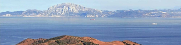
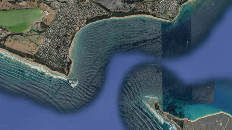
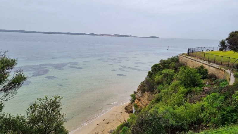
Port Phillip Heads is the sole connection between Port Phillip Bay and Bass Strait — meaning every seaborne cargo for Melbourne and Geelong passes through The Rip. The entrance between Point Lonsdale and Point Nepean spans about 3.5 km, but reefs and the shallow Rip Bank outside the heads reduce the navigable channel to roughly 1 km, cut by a canyon with depths approaching 100 m and near-vertical walls.
The operational regime reflects the hazard. Pilotage is compulsory: large vessels transit under the direction of Port Phillip Sea Pilots along a precise S-shaped course guided by leading lights, with movements controlled by the Point Lonsdale Signal Station. And there is no recommended anchorage in the approaches — a vessel that misses its window must ride it out at sea.
02 WHAT THE DATA SHOW
Published hydrodynamics of The Rip reveal why it behaves differently from a normal tidal entrance:
- Speed — tidal streams run at 6 knots (~3 m/s) under normal conditions and may exceed 9 knots in extreme conditions; formal studies for the channel-deepening project measured currents in excess of 3.5 m/s.
- Vertical structure — measured profiles show about 1.5 m/s near the surface, decreasing with depth, then strengthening again near 50 m — strong vertical shear that a surface-only measurement would entirely miss.
- Timing — the tidal stream does not turn at high and low water. Outside the heads the tide is a progressive wave; inside the bay it stands. The level difference between inside and outside peaks at high/low water — and so do the currents. Slack water occurs about three hours before and after high water.
- Complexity — the ebb forms a jet with strong eddies west of Shortland Bluff, and the canyon hosts vortices, upwelling and very confused seas. Winds and barometric pressure shift slack timing by ±40 minutes and tide heights by ±25 cm.
03 WHERE CURRENTS THREATEN OPERATIONS
Pilotage on the S-course
A 3.5 m/s cross-flow on a 300 m vessel inside a 1 km channel leaves no margin for error; the S-shaped course exists because the current field curves through the entrance.
Under-keel clearance
Sea-level gradients across Rip Bank exceed 0.3 m over roughly 1 km — a vessel's actual clearance depends on where and when it crosses, flagged in official studies as of particular practical significance for port operations.
Speed accounting
In the South Channel, vessel speed is measured through the water rather than over the ground — a direct acknowledgement that the tidal stream dominates ground-track calculations.
Hazard combinations
The most dangerous condition is an ebb stream against a strong southerly wind or heavy swell, producing large breaking seas across the entrance — conditions every pilot must forecast before boarding.
04 MEASUREMENT STRATEGY BY ZONE
The measurement answer follows the physics — three geometries for three distinct problems:
| Zone | Challenge | Approach |
|---|---|---|
| Navigable channel (wall-adjacent, <20 m) | Real-time cross-flow for pilotage windows | Fixed side-looking horizontal ADCP on channel infrastructure, continuous output to the signal station |
| Canyon (to ~100 m) | Strong shear near 50 m; eddies and vortices | Mooring or vessel-mounted 300 kHz profiling resolving the full vertical structure |
| Rip Bank (~20 m) | UKC gradients; wave–current interaction | Bottom-mounted 600 kHz profiler capturing shallow-bank flow and level-gradient forcing |
Two principles stand out from the published work. First, measure the full column: the shear structure means a surface-only sensor systematically understates the hazard at depth. Second, tie measurements to the standing-wave timing: any operational rule built on mid-tide slack will be wrong here.
05 THE OCEANTEK SOLUTION
Oceantek's ADCP portfolio maps directly onto the three-zone strategy. All instruments share a titanium housing, ±5 m/s default velocity range (extendable to ±20 m/s) and standard PD0 output.

HADCP-600
Horizontal ADCP · 600 kHz- 90 m horizontal range
- ±20 m/s velocity range
- 20 m depth rating, pier/wall mount
- 2 horizontal beams + 1 vertical
Role: continuous cross-flow across the navigable lane, fed to pilotage and signal-station operations;
View product →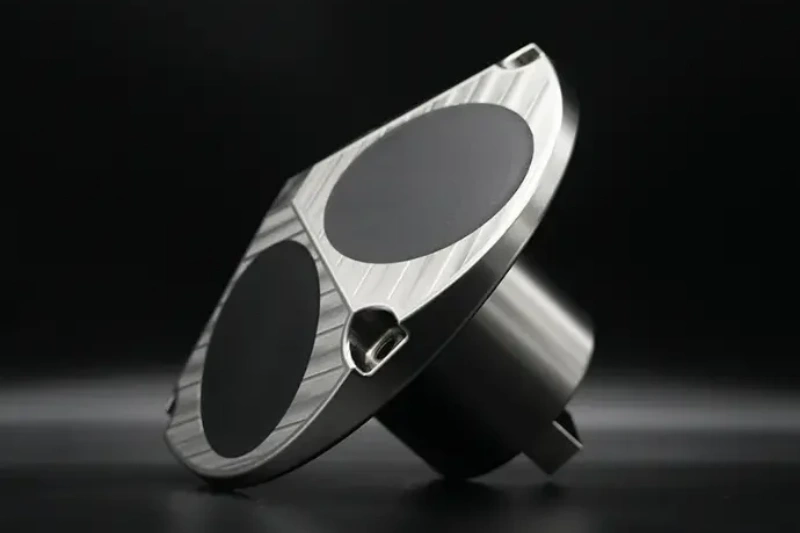
Ocean-ADCP-300-FA4
Ocean ADCP · 300 kHz- 160 m profiling range
- ±20 m/s, 1–8 m cells
- Vessel-mount or mooring
- ≤10 W · PD0 output
Role: resolves the mid-column strengthening near 50 m and the eddy structure in the ~100 m canyon.
View product →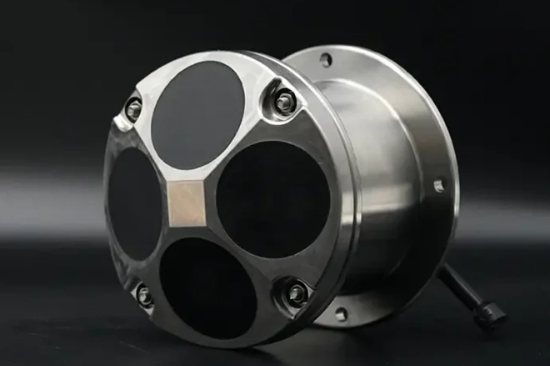
Ocean-ADCP-600-FA4
Ocean ADCP · 600 kHz- 70 m profiling range
- ±20 m/s, ±0.3% accuracy
- Titanium housing to 6000 m
- ≤10 W · self-contained ≥100 days
Role: high-resolution profiles on the ~20 m Rip Bank where level gradients govern under-keel clearance.
View product →The natural configuration is a three-layer entrance system: a wall-mounted HADCP-600 for the lane the pilots use, a 300 kHz profiler for the canyon physics, and 600 kHz bottom units on the bank that decides clearance.
06 FIELD NOTES
- Wall-mount everything you can — where the navigable lane runs close to channel infrastructure, a side-looking instrument measures the lane without living in the breaking seas.
- Expect heavy vertical shear, size cells accordingly — the flow weakening then re-strengthening near 50 m demands small cells (1–2 m) through the shear zones.
- Account for non-tidal forcing — wind and pressure shift slack timing by ±40 minutes; pair current data with local wind and pressure so pilots see the effective window, not the astronomical one.
- Plan servicing around the real slack — at an entrance where slack is three hours off the tide's high/low water, deployment windows must be computed from the local standing-wave physics.
🎯 Managing a High-Current Port Entrance?
Real-time cross-flow for pilotage, canyon shear profiling and bank-level UKC support — the full entrance-measurement chain.
🔍 Explore Ocean ADCP SeriesAlso see: HADCP-600 Horizontal ADCP · Questions? Contact our technical team