When selecting an Acoustic Doppler Current Profiler (ADCP), one of the most consequential — yet frequently overlooked — decisions is beam configuration. A 4-beam, 5-beam, and 9-beam ADCP are not simply incremental upgrades. Each represents a fundamentally different approach to extracting information from the underwater environment, with distinct trade-offs in cost, data quality, and deployment complexity.
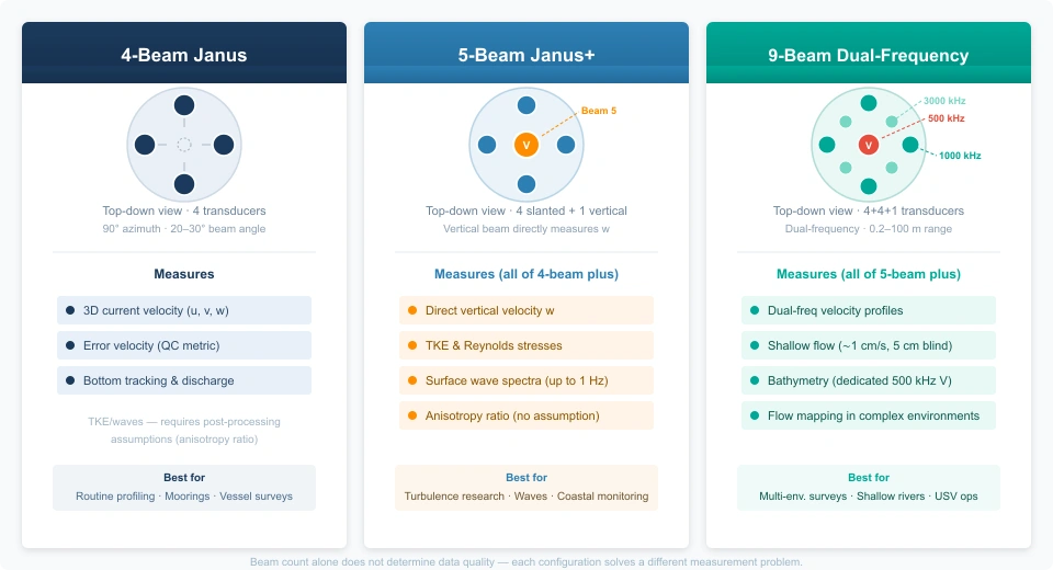
Why More Beams Do Not Always Mean Better ADCP Performance
The number of beams in an ADCP is not simply about measurement accuracy — it determines how much information the instrument can extract from a three-dimensional flow field. A common misconception is that more beams automatically mean better data. In reality, each configuration solves a different measurement problem, and adding beams introduces real trade-offs: higher power consumption, increased data bandwidth, greater computational complexity, and higher instrument cost.
A 4-beam ADCP remains the right choice for most current profiling applications. A 5-beam or 9-beam configuration becomes necessary only when your measurement objectives explicitly demand what those extra beams provide — direct vertical velocity measurement, turbulence quantification, or simultaneous multi-frequency flow mapping. The key is not maximizing beam count but matching beam geometry to the physical quantities you need.
Think of it this way: a 4-beam ADCP delivers a robust, time-tested estimate of three-dimensional current velocity. A 5-beam ADCP adds one critical piece of information — the directly measured vertical velocity component — which unlocks turbulence and wave measurements that a 4-beam system can only approximate. A 9-beam ADCP, typically a dual-frequency system, effectively operates as two ADCPs in one housing, extending the operational envelope across dramatically different water conditions. Each step up solves a specific, well-defined problem — not a general improvement in “accuracy.”
How ADCP Beam Configuration Works
An ADCP transmits short acoustic pulses along narrow beams into the water column. Suspended particles, plankton, and sediment scatter sound back toward the transducer. Because scatterers move with the water, the returning echo is Doppler-shifted — its frequency changes depending on whether the scatterers are moving toward or away from the instrument. By measuring this shift along multiple beams at known angles, the ADCP reconstructs the three-dimensional velocity vector at each depth cell.
The standard beam geometry is the Janus configuration: beams arranged in opposing pairs, typically angled 20°–30° from vertical and spaced 90° apart in azimuth. In a 4-beam Janus ADCP, one pair lies fore-aft and the other port-starboard. Differencing opposing beams isolates horizontal velocity components; summing returns from all four beams yields the vertical component. This works well when the flow is reasonably homogeneous across the beam spread, but it inherently relies on assumptions about spatial uniformity.
This is where beam count becomes critical. A 4-beam system provides one redundant measurement — four beams for three unknowns — enabling an “error velocity” quality-control check. A 5-beam system adds a dedicated vertical beam that directly measures vertical velocity, bypassing the homogeneity assumption. A 9-beam system, exemplified by the CHCNAV RiverStar 3600D, uses independent beam sets at different frequencies to cover a much wider range of depths and flow conditions in a single deployment.
4-Beam ADCP: The Industry Standard for Current Profiling
The 4-beam Janus ADCP has been the workhorse of current measurement for over four decades. Its dominance comes from a beam geometry that balances measurement capability against complexity, cost, and reliability.
Technical Concept
Four transducers are arranged symmetrically around the instrument axis, each tilted outward at 20°–25° (up to 30° in shallow-water models). Beams 1 and 3 form one opposing pair (fore-aft), Beams 2 and 4 the orthogonal pair (port-starboard). The along-beam velocity each transducer measures is the projection of the true 3D velocity vector onto that beam direction.
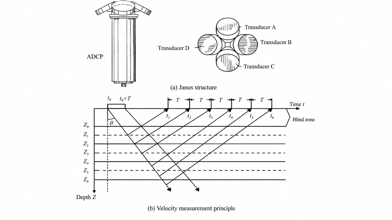
Subtracting opposing beam measurements cancels systematic bias and doubles the horizontal velocity signal. Summing returns from all four beams, combined with the known beam angle, yields the vertical component. With four beams measuring three unknowns (u, v, w), the system is overdetermined — the redundancy provides error velocity, a built-in data-quality metric. A large error velocity signals that the flow is not horizontally homogeneous across the beam footprint.
Beam Symmetry Reduces Errors
The Janus geometry’s defining advantage is error cancellation through symmetry. Because opposing beams are tilted at identical angles in opposite directions, homogeneity errors tend to cancel. A linear shear across the beam spread produces equal and opposite biases in the opposing pair. This symmetry also makes the 4-beam ADCP relatively insensitive to pitch and roll on moving vessels — differential motion between opposing beams cancels out.
The 4-beam configuration also minimizes physical footprint: fewer transducers mean a smaller, lighter housing, lower power consumption, simpler electronics, and fewer failure points. For long-duration autonomous deployments where battery life and reliability are paramount, these practical advantages often outweigh the theoretical benefits of additional beams.
Why Does 4-Beam ADCP Remain Dominant?
First, for the most common application — mean current profiling — 4-beam accuracy (±0.5% of measured velocity or better) is fully adequate. Second, the 4-beam ADCP benefits from a massive installed base with decades of validated deployment experience. Processing algorithms, QC procedures, and best practices are mature and well-documented, reducing project risk. Third, 4-beam instruments are the most cost-effective across all frequency bands. For multi-instrument arrays, the per-unit savings can be decisive.
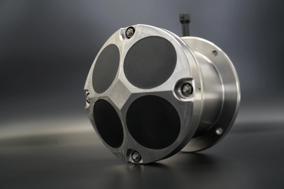
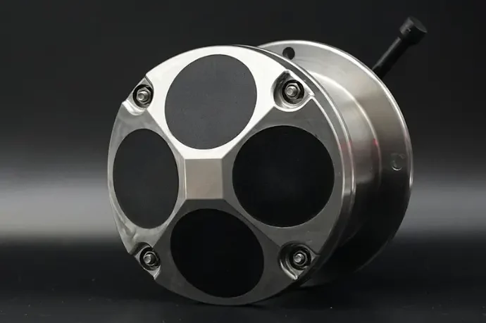
Oceantek 4 beam configuration 600kHz adcp
Notably, with advanced post-processing techniques like the variance method or structure function method, 4-beam data can yield TKE dissipation rates and Reynolds stresses — parameters once thought to require a 5-beam instrument. These methods involve anisotropy and homogeneity assumptions, but in many real-world flows they agree well with independent microstructure profiler measurements.
4-Beam ADCP Is Optimized For:
- Mean current velocity profiling — measuring speed and direction at multiple depths for navigation, offshore operations, and oceanographic research
- Long-duration autonomous deployments — where battery life, size, and per-unit cost are the primary constraints
- Bottom-tracking and discharge measurement — vessel speed over ground and total volume transport in rivers, estuaries, and channels
- Vessel-mounted underway surveys — where Janus geometry’s pitch-and-roll immunity is essential
- Multi-instrument arrays — where deploying many cost-effective instruments beats a few expensive ones for spatial coverage
- Standard oceanographic moorings — basin-scale circulation, boundary currents, and transport monitoring
5-Beam ADCP: Why Vertical Velocity Matters
A fifth vertical beam is added to the traditional four-beam Janus system. This seemingly minor addition — one extra transducer pointing straight up (or down) — fundamentally changes what the instrument can measure. The vertical beam, or Beam 5, operates as an independent echo-sounder that directly tracks vertical scatterer motion and the water surface position.
Why Is the Fifth Beam Important?
In a 4-beam ADCP, vertical velocity w is derived indirectly by solving equations that assume the flow is statistically uniform across the beam spread. At a 20° beam angle and 100 m range, the four beams sample a circle roughly 73 m in diameter. If the flow contains turbulent eddies or internal waves smaller than this footprint, the homogeneity assumption breaks down and calculated w becomes unreliable.
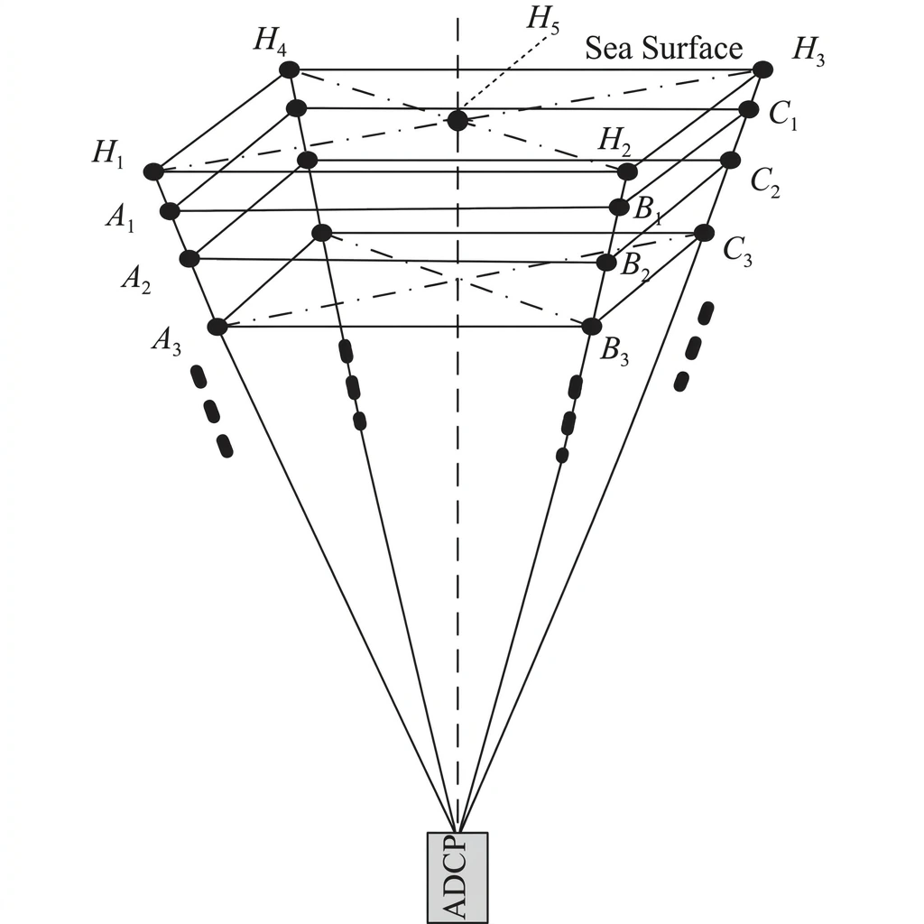
Schematic Diagram of Five-Beam Space
The fifth beam solves this by measuring the vertical component directly at the instrument’s location — no spatial uniformity assumption needed. For turbulence studies, this is transformative. TKE is defined as half the sum of velocity component variances; without reliable vertical velocity variance, 4-beam TKE estimates must assume a turbulence anisotropy ratio. Research by Togneri et al. (2017) showed that while the assumed anisotropy ratio averages within 3.4% of the true 5-beam value, errors can be much larger during intermittent turbulent events — precisely the conditions of greatest scientific interest.
What Does This Enable?
1. Better Turbulence Measurement
Direct vertical velocity from Beam 5 enables full TKE estimation without an anisotropy assumption. It also improves Reynolds stress estimates — the turbulent momentum fluxes driving ocean mixing — by providing independent, co-located measurements of all three velocity components. This matters because turbulent mixing controls heat, nutrient, pollutant, and dissolved gas transport throughout the water column. In coastal environments, where tidal flows, wave breaking, and river plumes generate turbulence that drives ecosystem productivity, a single 5-beam ADCP replaces what traditionally required separate microstructure profilers.
The vertical beam also measures turbulence anisotropy itself — a quantity 4-beam processing simply assumes. Knowing whether turbulence is isotropic or anisotropic is critical for selecting appropriate closure schemes in numerical ocean models.
2. Wave Measurement Capability
Beam 5 doubles as a high-resolution acoustic rangefinder, tracking surface rise and fall with each passing wave. Surface elevation time series yield non-directional wave spectra: significant wave height, peak period, and spectral shape.
Studies comparing 5-beam ADCP measurements against co-located wave buoys show excellent agreement. Bouferrouk et al. (2016) reported that ADCP surface elevation spectra matched buoy data in the 0.10–0.35 Hz band, with the ADCP showing better low-frequency swell sensitivity during low-energy sea states. Spectral parameters agreed to within 2–7%. The vertical beam measures waves up to ~1 Hz, covering the full wind-sea and swell range.
Combined with orbital velocity measurements from the four slanted beams — which resolve wave direction — a single 5-beam ADCP delivers complete directional wave spectra: height and period from Beam 5, direction and spreading from the Janus beams. One deployment, one instrument, three capabilities: current profiler, wave buoy, and turbulence measurement system.
5-Beam ADCP Is Optimized For:
- Turbulence and mixing studies — direct TKE, Reynolds stress, and anisotropy measurement without assumed isotropy
- Wave-current interaction research — simultaneous directional wave spectra and current profiles from one instrument
- Coastal and estuarine monitoring — environments where waves, turbulence, and currents all affect sediment transport and ecosystem health
- Offshore renewable energy site assessment — combined wave and current resource characterization for project planning
- Internal wave detection — vertical beam resolves sharp displacements with higher fidelity than slant-beam processing
- Near-surface current measurement — vertical beam avoids side-lobe interference that limits slant beams near boundaries
- Scientific research — incremental cost of the fifth beam is justified by eliminating anisotropy assumptions
9-Beam ADCP: From Velocity Measurement to Flow Mapping
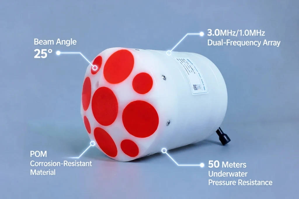
If the 5-beam ADCP adds a vertical dimension, the 9-beam ADCP adds a spectral dimension — simultaneous multi-frequency profiling from a single instrument. A modern 9-beam ADCP like the CHCNAV RiverStar 3600D is effectively two independent ADCPs in one compact housing, each optimized for a different operational regime.
Why Add More Beams?
The core challenge is the trade-off between frequency and range. High-frequency sound (e.g., 3600 kHz) delivers exceptional resolution and can measure flows as low as 1 cm/s with 1 mm/s precision, but attenuates rapidly — range is limited to 10–15 m. Low-frequency sound (600–1200 kHz) reaches 100 m or more but with coarser resolution and higher uncertainty in slow flows.
In the RiverStar 3600D: four beams at 1200 kHz for deeper profiling, four beams at 3600 kHz for high-resolution shallow measurement, and one vertical beam at 600 kHz for bottom tracking and depth. The instrument intelligently switches between beam sets based on conditions, covering 0.2–100 m depth from a single device — versatility that previously required multiple single-frequency ADCPs.
Beyond dual-frequency coverage, the overlapping beam patterns illuminate the water column from multiple angles and scales, improving data quality in complex flows — bridge pier wakes, strong-shear tidal channels, or river confluences where water masses of different velocity and sediment load merge.
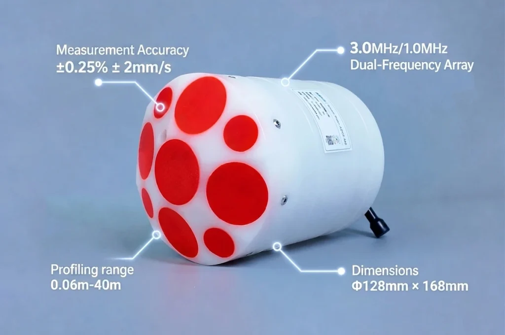
Oceantek River-ADCP-M9 9-beam acoustic Doppler current profiler with compact size Φ128mm × 168mm
The near-surface blind zone shrinks to as little as 5 cm in high-frequency mode (vs. 25–50 cm for typical single-frequency ADCPs) — significant for shallow-water discharge where every centimeter matters. The vertical beam’s bottom-tracking also enables simultaneous bathymetric mapping, eliminating a separate echo-sounder.
9-beam ADCPs are a recent commercial development, driven by transducer miniaturization and demand for multi-purpose survey instruments. They offer impressive versatility but add complexity in data management and processing. Adoption should be based on a clear operational need for multi-frequency coverage — not on the assumption that nine beams are inherently superior.
9-Beam ADCP Is Optimized For:
- Multi-environment hydrographic surveys — one instrument for shallow rivers (<1 m) through deeper coastal waters (>50 m)
- High-resolution shallow-water discharge — low-velocity flows in streams, canals, and engineered channels where single-frequency ADCPs struggle
- USV and autonomous platform deployments — compact (~2 kg, 12 cm diameter) and compatible with small unmanned vessels
- Simultaneous bathymetry and velocity mapping — vertical beam bottom-tracking replaces a separate echo-sounder
- Complex flow environments — bridge scour, tidal channels, river confluences, hydropower intakes and tailraces
- Diverse survey portfolios — teams working across rivers, lakes, estuaries, and coastal zones who would otherwise maintain multiple ADCPs
Which ADCP Beam Configuration Should You Choose?
The answer depends on what you need to measure and where. The table below summarizes the decision logic.
| Your Application | Recommended Configuration | Rationale |
|---|---|---|
| Standard current profiling — moorings, vessel-mounted surveys, transport monitoring | 4-Beam ADCP | Proven accuracy, lowest cost, longest battery life, mature processing tools |
| Turbulence and mixing research — TKE, Reynolds stresses, dissipation rates | 5-Beam ADCP | Direct vertical velocity eliminates anisotropy assumption; full turbulence characterization |
| Combined wave and current measurement — coastal monitoring, offshore energy | 5-Beam ADCP | Vertical beam for surface tracking and wave spectra; slant beams for directional information |
| Multi-environment surveys — shallow rivers to coastal waters in one campaign | 9-Beam ADCP | Dual-frequency beam sets auto-adapt to depth and flow conditions |
| High-resolution shallow-water discharge — streams, canals, irrigation channels | 9-Beam ADCP | High-frequency beams measure velocities <1 cm/s with 5 cm near-surface blanking |
| Large-scale observing networks — simultaneous multi-site deployments | 4-Beam ADCP | Per-unit cost advantage enables greater spatial coverage across a region |
Resist the temptation to default to the highest beam count your budget allows. Start by defining your measurement requirements: What quantities do you need? Over what depth range and flow conditions? What is your acceptable uncertainty? Map those answers to the right configuration. In many cases, a 4-beam ADCP meets your needs. When it does not — when you need turbulence statistics, wave spectra, or multi-frequency coverage — the 5-beam or 9-beam configuration becomes the right tool.
Also consider total cost of ownership. A 5-beam or 9-beam ADCP generates more data and demands more sophisticated processing. The most expensive ADCP is not the one with the highest price tag — it is the one whose capabilities you pay for but never use.
Ready to Find the Right ADCP for Your Application?
Choosing the correct beam configuration is one of the most important decisions in planning a successful measurement campaign. Whether you need a rugged 4-beam ADCP for long-term moorings, a 5-beam instrument for combined wave and turbulence studies, or a versatile 9-beam system for multi-environment surveys, matching the instrument to your objectives is essential.
At Oceantek, we supply ADCPs across all three beam configurations, backed by application engineering expertise across oceanographic research, offshore engineering, hydropower monitoring, and environmental assessment. Contact our technical sales team to discuss your requirements, request a quotation, or schedule a demonstration.
Explore Oceantek’s ADCP product range or get in touch with our application engineers to start the conversation.